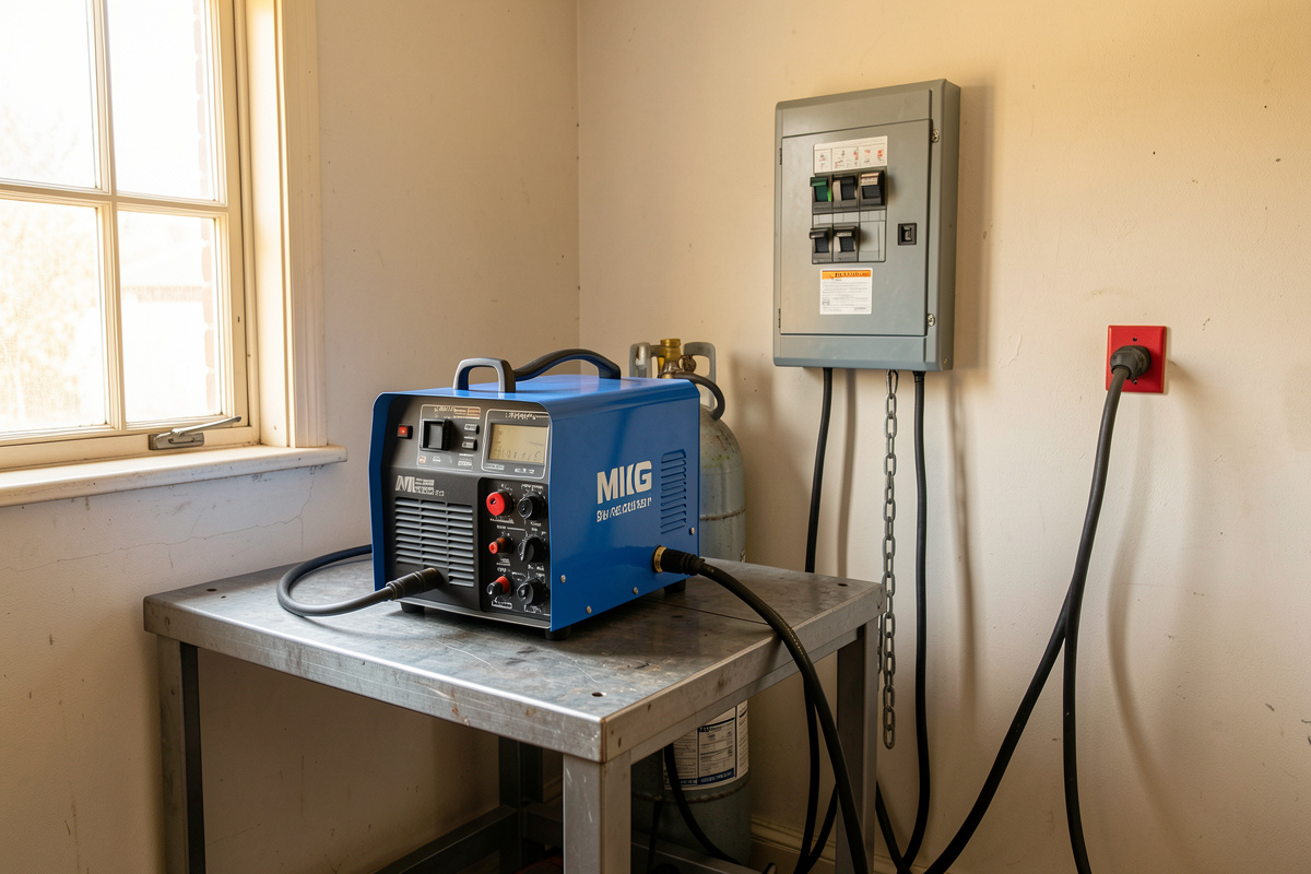

A home welder needs a circuit sized to its input draw, not its output amps: most 120V machines want a dedicated 20-amp circuit on 12-gauge copper, while a 200-amp class 240V welder like the YesWelder MIG-PRO205DS I run wants a 40- to 50-amp breaker on 8- or 6-gauge wire. Get that pairing right and the arc is rock-steady. Get it wrong and you buy tripped breakers, a sagging arc, or a warm spot in the wall you really don’t want.
I learned the hard way that a welder is only as good as the power feeding it. Years back I plugged my MIG-PRO into a long, skinny extension cord to reach a job at the far end of the shop, and the arc kept stuttering out on 6 mm plate. I chased wire speed, gas, tip size — everything but the real culprit. The machine was starving. The power on the far end of that cord had sagged low enough that the inverter couldn’t hold an arc under load. That one afternoon taught me more about shop wiring than any spec sheet, and it’s why this whole cluster exists.
Here in my Sweden workshop everything is 230V single-phase, so I don’t get to pretend 120V circuits are optional — they barely exist here. Most of you reading this are on North American split-phase, choosing between a 120V outlet and a dedicated 240V circuit, wrestling with NEC, NEMA plugs, and AWG copper. So I’ve built this guide around that world, using the same machine I plug into both 110V and 220V every week to show you exactly what changes. Let’s get your shop powered properly.
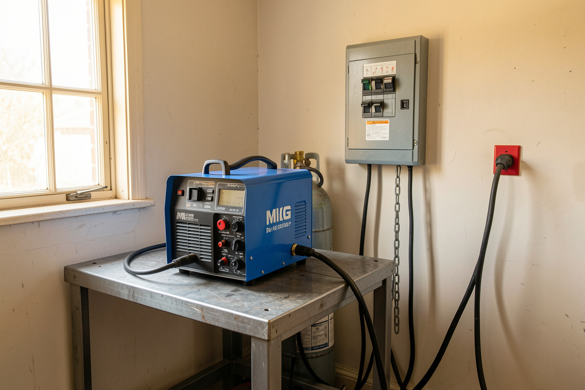
How Much Power Does a Home Welder Actually Need?
A home welder needs enough clean voltage and current to hold its arc under full load without sagging or tripping the breaker. In practice that means a dedicated circuit: 20 amps at 120V for small machines, or 30–50 amps at 240V for anything you’d run on 5 mm-plus steel. The exact number lives on your machine’s nameplate, not in a marketing headline.
The number everyone quotes — “200 amp welder,” “140 amp MIG” — is output current, the amperage hitting the puddle. That is not what your wall has to supply. Your circuit feeds the input side, and because a welder is a step-down transformer or inverter, it pulls far fewer amps on the input than it pushes on the output. My MIG-PRO205DS can throw 205 output amps, but on 240V it only draws somewhere in the mid-20s on the input side at that setting. High voltage in, high current out — that trade is the whole reason a modest house circuit can run a serious welder.
The catch is duty cycle. A welder doesn’t pull that input current continuously; it pulls it in bursts while the trigger is down. That intermittent nature is baked into how these circuits are sized and protected, and it’s why welding gear gets its own chapter in the electrical code. Understand that one idea and everything else — breaker size, wire gauge, why the numbers look “too big” — falls into place.
Reading Your Welder’s Nameplate: Input Amps vs Output Amps
Your welder’s nameplate is the single source of truth for sizing its circuit. Ignore the box, ignore the model number, and find the plate on the back or bottom of the machine. Two markings matter most: I1max, the maximum primary (input) current the machine can draw, and I1eff, the effective input current averaged over its rated duty cycle. Those two figures, plus your supply voltage, tell an electrician everything.
On my bench I keep a clamp meter on the input lead when I’m dialing in a new machine, because the plate gives you the design maximum and I like to know the real draw at the settings I actually weld. The first time I did this to the MIG-PRO on 220V, running a fillet on 6 mm steel, the clamp settled far below the plate’s I1max — exactly what you’d expect, since I wasn’t welding at the machine’s absolute ceiling. If you want to actually measure your own draw, a clamp meter is the cheapest education in shop electrical you’ll ever buy.
Here’s the part beginners miss: a dual-voltage machine has two sets of input numbers. Run it on 120V and it draws roughly double the input amps it does on 240V for the same output, because it’s making the same power (watts) from half the voltage. That’s the entire argument in the 110V vs 220V welder question, and it’s why I run my MIG-PRO on 220V for anything past thin sheet — the 120V side simply runs out of input headroom.
As an Amazon Associate I earn from qualifying purchases.
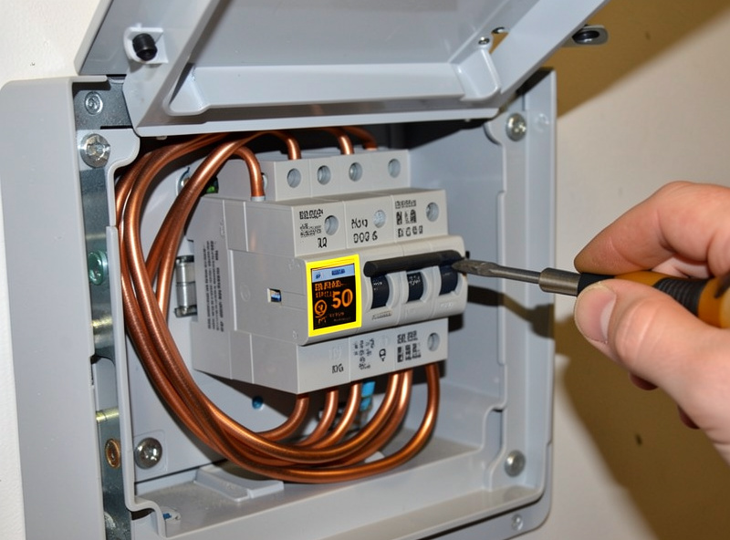
120V or 240V: Which Circuit Does Your Home Shop Need?
If you only ever weld sheet metal and light brackets under about 4 mm, a good 120V/20-amp circuit will carry you. The moment you want to burn into 6 mm and thicker, or run stick, or keep a long duty cycle without heat-cutting the machine back, you want a dedicated 240V circuit. The higher voltage gives the welder more power to work with and pulls fewer amps doing it.
I’ve run my dual-voltage MIG-PRO on both, back to back, on the same joint. On the 120V adapter it does fine on thin stuff, but push it into thicker steel and you feel it choke — the machine’s own overload protection reins the output back so it doesn’t exceed what a 120V, 20-amp feed can deliver. Flip it to 220V and the same machine walks a fat, hot bead into plate that the 120V side wouldn’t touch. Same welder. Different wall.
The practical rule I give every beginner: a 120V circuit is a great starter and a lousy ceiling. If you’re wiring anything new, wire 240V. You will grow into it, and retrofitting later — running new cable, adding a breaker, mounting a 240V welder outlet — costs more the second time around. For the full breakdown of what each voltage actually gets you at the puddle, I dug into it in the 110V vs 220V power guide. And if you’re still assembling a shop, my first-year equipment checklist puts the circuit decision in context with the rest of the gear.
What Breaker and Wire Size for Each Welder Size?
Match the breaker and wire to the welder’s rated input, then verify against your nameplate. As a starting map, here are the pairings I see most often on home machines. Treat this as typical ranges to sanity-check your own numbers against — the plate on your welder and your local code have the final say, and the full walk-through lives in the breaker and wire size chart.
| Welder class (output) | Supply | Typical input draw | Common breaker | Min. copper wire | Outlet |
|---|---|---|---|---|---|
| Small flux-core / MIG, 90–140A | 120V | ~18–20A | 20A | 12 AWG | NEMA 5-20 |
| Dual-voltage MIG on 120V side | 120V | ~20A | 20A | 12 AWG | NEMA 5-20 |
| 200A class MIG/inverter on 240V | 240V | ~24–30A | 40A | 8 AWG | NEMA 6-50 |
| 200–250A stick / multiprocess | 240V | ~35–45A | 50A | 6 AWG | NEMA 6-50 |
| 250–300A shop machine | 240V | ~45–50A | 50–60A | 6–4 AWG | NEMA 6-50 |
| Plasma cutter, 40–65A cut | 240V | ~20–35A | 40–50A | 8–6 AWG | NEMA 6-50 |
Two things to notice. First, the breaker is often bigger than the machine’s average draw — that’s not sloppy, it’s deliberate, and I explain why below. Second, wire gauge is not optional trim: 6 AWG copper is the workhorse for a 50-amp welder circuit, and dropping to a thinner gauge to save a few dollars is how you end up with warm wire and voltage drop. The plain-English breaker and wire chart covers aluminum wire, conduit fill, and the 60°C-versus-75°C column that trips people up.
Why NEC Article 630 Lets a Welder Sit on a “Too-Big” Breaker
Under the U.S. National Electrical Code, welders get their own set of rules in Article 630, and it looks strange until you understand duty cycle. For a normal continuous load — a heater, a motor — you size the breaker close to the load. For a welder, the code lets the overcurrent device run as high as 200% of the machine’s rated input current, and the conductors are sized on the duty-cycle-adjusted current rather than the raw maximum.
Why the generosity? Because a welder is an intermittent load. It hammers the circuit for a few seconds while you lay a bead, then idles while you reposition, chip slag, or re-clamp. The wire never sees continuous full current long enough to overheat, and the oversized breaker keeps the machine’s big inrush from nuisance-tripping every time you strike an arc. That’s the whole logic. It’s also why you can’t reason about a welder circuit the way you’d reason about a wall of receptacles. If you want the authoritative language, the code itself is published by the National Fire Protection Association as NFPA 70, and any licensed electrician sizing a welder circuit will be working from Article 630.
I’ll be straight about the boundary of my own authority here: I run machines, I don’t pull permits. Panel work, code-letter breaker selection, and final circuit design are a licensed electrician’s job, and my welder friend Mike — decades in the trade — has talked me out of “just adding a breaker myself” more than once. Know the theory so you can hold an intelligent conversation with your electrician; don’t use it as a license to freelance inside a live panel.
Adding a Dedicated 240V Circuit: Outlets and When to Call an Electrician
A dedicated 240V welder circuit is a home run from your panel to a single outlet, on its own breaker, with no other loads sharing it. For most home welders that outlet is a NEMA 6-50 (two hots and a ground, no neutral) or a NEMA 14-50 (adds a neutral, the same plug an electric range or EV charger uses). Which one you install depends on your machine’s plug and whether you ever want to share the circuit with a non-welding load.
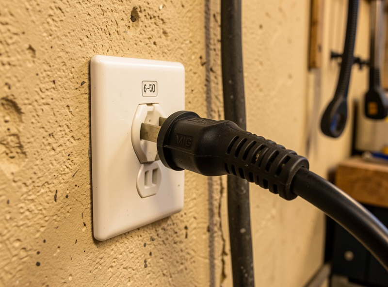
The 6-50 is the traditional welder outlet: simpler, three conductors, and every 240V welder I’ve handled ships with or accepts a 6-50 plug. The 14-50 has become common because it’s the EV and RV standard, so parts are everywhere — but it forces you to run a neutral you don’t strictly need for a welder. I walk through the real trade-offs, the wire count, and exactly where the line is between DIY and “call a pro” in wiring a 240V welder outlet.
My honest line on this: mounting and wiring a receptacle on an already-installed, correctly-sized, de-energized circuit is within reach of a careful DIYer in many places. Adding the breaker, running the home run, and anything involving the panel bus is electrician territory unless you are genuinely qualified and it’s legal where you live. A welder outlet wired wrong doesn’t announce itself — it works fine until the day it doesn’t. When in doubt, pay the pro. The welding electrical safety guide covers the shock and grounding hazards that make this non-negotiable.
Can You Run a Welder on a Generator?
Yes, a welder will run on a generator — but only if the generator is big enough and clean enough. “Big enough” means it can supply the welder’s surge and running watts with headroom; “clean enough” means low total harmonic distortion so the machine’s electronics don’t get cooked. Undersize either dimension and you get a dying arc at best, a fried inverter at worst.
Sizing is the first hurdle. A welder’s input in watts is roughly its input voltage times its input amps, and you want a generator that comfortably exceeds that with margin for the startup surge. A small 120V flux-core machine wants a real 3,500–4,000 running watts as a floor, and honestly more; a 200-amp 240V machine wants a 240V-capable generator in the 7,000-watt-plus class. I lay out the actual math — running watts, surge, and how to read your welder’s draw into a generator spec — in running a welder on a generator.
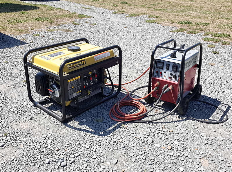
The second hurdle is power quality, and it’s the one that quietly kills machines. Modern inverter welders rectify incoming AC and are sensitive to voltage spikes and dirty waveforms. A conventional open-frame generator can put out ragged power with high harmonic distortion; an inverter generator produces a clean sine wave that a welder’s electronics can stomach. Before you plug a nice inverter welder into any generator, read will an inverter welder run on a generator — the THD and damage-risk piece — because “it powered on” is not the same as “it’s safe to run.”
Voltage Drop: The Silent Arc-Killer on Long Runs
Voltage drop is what happens when current pushes through undersized or overlong wire and loses voltage to resistance along the way. For a welder, that lost voltage shows up as an arc that stutters, sags, and lacks penetration — the exact symptom that sent me chasing ghosts on that skinny extension cord years ago. The wire wasn’t broken. It was just too thin and too long for the current, and the far end sagged below what the inverter needed.
The rule of thumb electricians work to is keeping branch-circuit voltage drop under about 3%. Every foot of cable adds resistance, so a long run needs a fatter conductor than a short one to carry the same current without sagging. This bites two ways in a real shop: the fixed wiring from your panel to a far outlet, and — far more commonly — the extension cord you reach for to weld away from the bench. I keep a heavy Iron Box cord sized specifically so my inverter isn’t starved on a long pull, because I’ve felt what the alternative does to a bead.
If you weld anywhere but right at the outlet, read voltage drop that kills your arc and my dedicated welding extension cord gauge guide. Between them they’ll stop you from ever blaming the machine for what the cord is doing. Reference tables and voltage-drop calculators from wire makers like Southwire are worth bookmarking too.
When Your Welder Keeps Tripping the Breaker
A welder that trips the breaker is telling you one of three things: the circuit is too small for the machine, the breaker is the wrong type or tired, or the welder itself is faulting. The order you check them in matters, because swapping in a bigger breaker to “fix” a genuinely undersized circuit is how wiring fires start. Never up-size a breaker beyond what the wire is rated to carry.
Most nuisance trips on home welders come down to running a 240V-hungry machine on a 120V circuit, stacking the welder on a shared circuit with other loads, or a long marginal extension cord dragging the input current up as voltage drops. The genuine faults — a shorted trigger, a failing rectifier — are rarer but real. I walk the whole decision tree, from “it’s the circuit” to “it’s the machine,” in welder keeps tripping the breaker.
Safety: The Electrical Hazards That Actually Hurt You
Welding power is not hobby-grade voltage you can be casual around. A 240V circuit will kill you as readily as any household 240V, and the combination of high current, a grounded steel workpiece, sweat, and gloves you keep damp is a genuine shock hazard. Treat every welder circuit as capable of hurting you, because it is.
The rules I hold to, and won’t bend on: one machine per dedicated circuit; a solid ground path all the way back to the panel; never bypass or defeat the ground pin; and never work inside a panel or on a circuit you haven’t personally confirmed is dead. Beyond shock, the welder’s own hazards stack on top — arc-eye, the fume plume (manganese from steel, and the zinc-oxide fever hazard the second you weld anything galvanized), and fire from a stray spark finding hidden combustibles. I keep those separate and covered in the electrical safety guide, and the broader hazard picture is one of the first things I hammer in the beginner’s complete guide. For the workplace-standard framing, the U.S. OSHA welding, cutting, and brazing pages are the reference I point people to.
Getting the power right is the unglamorous half of welding well. Nobody posts a hero shot of a correctly sized breaker. But every clean bead I’ve laid started with a machine that had the voltage and current it needed, on a circuit that could deliver it, through a cord that didn’t rob it. Nail the power, and the welding gets a whole lot easier to blame on yourself.
Does a welder’s amp rating tell me the circuit size I need?
No. The advertised amp rating is output current at the arc. Your circuit feeds the input side, which draws far fewer amps because the welder trades high voltage for high current. Size the circuit from the input current on the machine nameplate, marked I1max and I1eff, not the output rating.
Can I run a 240V welder on a regular household outlet?
No. A standard 120V household outlet cannot supply a 240V machine, and even a dual-voltage welder running on its 120V side is limited to lighter work. A 240V welder needs a dedicated 240V circuit with the correct breaker, wire gauge, and outlet such as a NEMA 6-50.
Why is the breaker on a welder circuit bigger than the machine’s draw?
Because a welder is an intermittent load. The U.S. National Electrical Code Article 630 allows the overcurrent device to be sized up to 200 percent of rated input current so the machine’s inrush does not nuisance-trip, while the wire is sized on the duty-cycle-adjusted current. The wire never sees continuous full current long enough to overheat.
What size wire does a 50-amp welder circuit use?
A 50-amp 240V welder circuit is typically run on 6 AWG copper. Thinner wire risks overheating and voltage drop, especially on long runs. Always confirm against your local code and the specific breaker and conductor ratings, and upsize the conductor for long distances to hold voltage drop under about 3 percent.
Will running my welder on a generator damage it?
It can, if the generator is undersized or produces dirty power. Inverter welders are sensitive to voltage spikes and high harmonic distortion. Use an inverter generator that produces a clean sine wave and comfortably exceeds the welder’s running and surge watts. A cheap open-frame generator can hold an arc yet still stress the machine’s electronics over time.
Do I need an electrician to add a welder outlet?
For anything involving the panel, a new breaker, or a new home-run cable, yes, unless you are genuinely qualified and it is legal where you live. Mounting a receptacle on an existing, correctly sized, de-energized circuit is within reach of a careful DIYer in many areas, but a welder circuit wired wrong can work fine until it fails. When in doubt, hire a licensed electrician.
Keep Building
- What Breaker and Wire Size Your Welder Needs: A Plain-English Chart
- 110V vs 220V Welders: How Much Power You Actually Need at Home
- Voltage Drop That Kills Your Arc: Long Runs and Undersized Circuits
- Running a Welder on a Generator: Watts, Surge, and Clean Power
- Adding a 240V Welder Outlet: NEMA 6-50 vs 14-50 and When to Call a Pro
- Welder Keeps Tripping the Breaker: Causes and the Real Fix

Discussion (0)