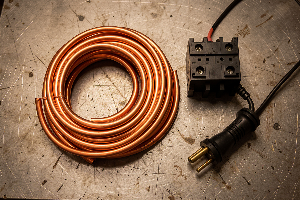

Size your welder circuit from the input current on the machine’s nameplate, then match the breaker and wire to it: a 20-amp input wants a 20-amp breaker on 12 AWG copper, a 40-amp input wants a 50-amp breaker on 6 AWG. The breaker protects the wire; the wire carries the load. Get that pairing right and you never think about it again.
The problem is that welder spec sheets shout the wrong number at you. “200 amp MIG” is the output at the arc — it has nothing to do with what your wall supplies. I’ve watched beginners try to wire a 50-amp circuit for a machine that draws 24 amps on the input, and others try to run a 240V machine off a 15-amp receptacle and wonder why it trips. This chart fixes both mistakes.
I run a YesWelder MIG-PRO205DS, and the first thing I did before it ever struck an arc was flip it around and read the plate. That two-minute habit is the whole game. Let me show you how to read it, then give you the plain-English chart.
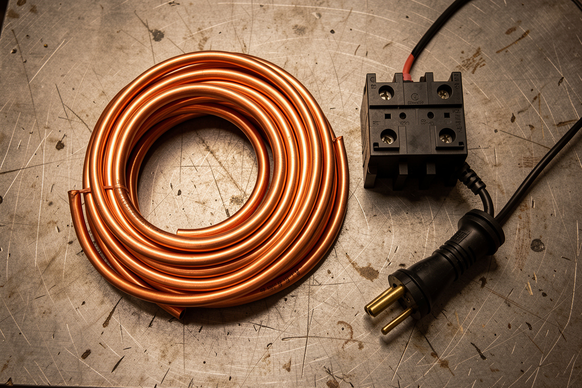
How Do I Read My Welder’s Nameplate to Size the Circuit?
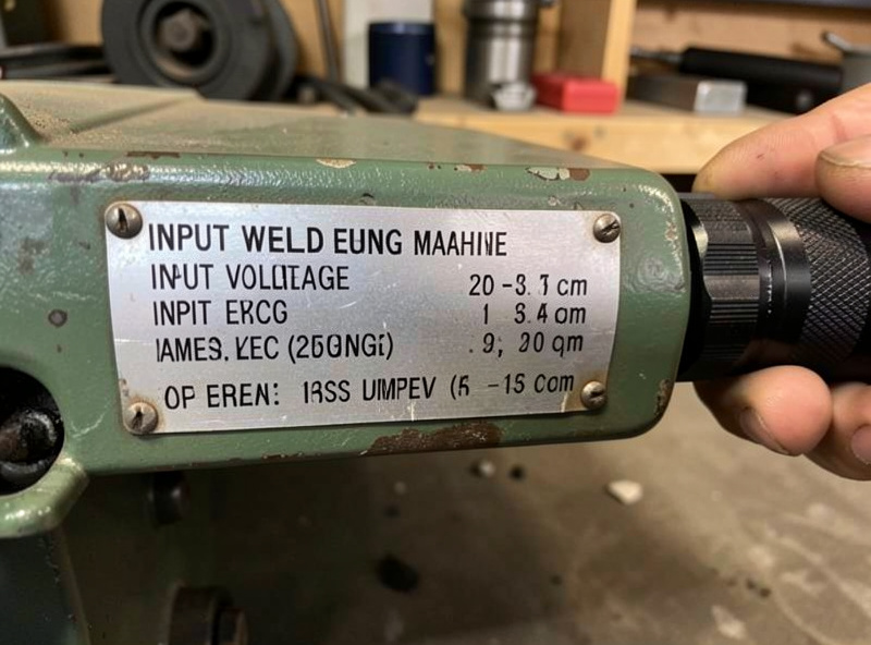
Find the nameplate on the back or bottom of the machine and look for two input-current figures: I1max (maximum primary current) and I1eff (effective current over the rated duty cycle). Those, plus your supply voltage, size the whole circuit. The output amperage — the big marketing number — plays no part in it.
On a dual-voltage machine the plate lists two rows, one for 120V and one for 240V, and the input amps roughly double on the 120V side because the machine makes the same power from half the voltage. My MIG-PRO shows a modest input on 220V and a much hungrier figure on 110V, which is exactly why I keep it on 220V for real work. If your plate is faded or missing — it happens on used machines — the manufacturer’s manual carries the same figures.
If you want to see the real-world number instead of the design maximum, clamp the input lead with an ammeter while you weld at your normal settings. I did this the week I got the machine — running a fillet on 6 mm steel, the clamp sat well below the plate’s I1max, because I wasn’t welding at the machine’s absolute ceiling. That measured draw is reassuring, but you still size the circuit off the nameplate maximum, not your comfortable middle setting. Design for the worst case, weld in the sweet spot.
Breaker and Wire Size Chart for Common Home Welders
Here’s the map for the machines that actually live in home shops. Copper conductors, standard 240V (or 120V where noted), reasonable run lengths under about 50 feet. Read your own nameplate and confirm against local code — this chart gets you 90% of the way and tells you what to verify.
| Input current (from nameplate) | Supply | Breaker | Copper wire (75°C) | Typical machine |
|---|---|---|---|---|
| Up to 15A | 120V | 15A | 14 AWG | Tiny flux-core |
| 15–20A | 120V | 20A | 12 AWG | Small MIG / dual-voltage on 120V |
| 20–25A | 240V | 30A | 10 AWG | Light 240V MIG |
| 25–32A | 240V | 40A | 8 AWG | 200A class MIG/inverter |
| 32–40A | 240V | 50A | 6 AWG | 200–250A stick / multiprocess |
| 40–48A | 240V | 60A | 6 AWG (or 4 for margin) | 250–300A shop machine |
Notice how the breaker sits a step above the input current in most rows. That gap is intentional and code-sanctioned, not a fudge — the next section explains it. Notice also that 6 AWG copper does a lot of heavy lifting: it’s the standard wire for a 50-amp welder outlet, and I’d rather see someone slightly over-gauge than starve a machine. The hub piece, welder power requirements for a home shop, puts these numbers in the wider context of choosing a circuit.
Why Is the Breaker Bigger Than My Welder’s Amp Draw?
Because a welder is an intermittent load, and the electrical code treats it differently from a steady load. Under NEC Article 630, the overcurrent device can be sized up to 200% of the machine’s rated input current, so the welder’s brief inrush doesn’t nuisance-trip the breaker every time you strike an arc. The conductors, meanwhile, are sized on the duty-cycle-adjusted current, not the raw peak.
Think about how you actually weld. Trigger down for a few seconds laying a bead, then up while you reposition, chip, re-clamp, check your fitup. The wire never carries full current long enough to heat up the way a continuously loaded circuit would. So the code lets the breaker ride higher to swallow the inrush, while the wire is sized on the honest average. This is why you can’t reason about a welder circuit the way you’d size a run of receptacles — and why a machine drawing 30 input amps legitimately lives on a 50-amp breaker. The code language is published by the National Fire Protection Association as NFPA 70; your electrician works from Article 630 for exactly this.
One hard limit, though: the breaker can never exceed the wire’s rating. Up-sizing a breaker to stop nuisance trips on genuinely undersized wire is how you turn a tripping annoyance into a wiring fire. The breaker protects the wire. If the wire can’t carry it, the wire is the thing you fix.
60°C or 75°C Wire — Which Column Do I Use?
Building wire is rated at different temperatures, and the ampacity tables in the code have separate columns for 60°C, 75°C, and 90°C insulation. For most home welder circuits the practical answer is the 75°C column, because the terminations on modern breakers and receptacles are rated for it. That’s the column my chart above uses.
The wrinkle is that for the smaller gauges — 14, 12, and 10 AWG — the code caps you at the 60°C values regardless of insulation, under the small-conductor rule. That’s why 10 AWG tops out at a 30-amp breaker even though its 75°C ampacity looks higher, and 12 AWG at 20 amps. Above 10 AWG you get the fuller 75°C numbers, which is where 8 AWG earns a 40-amp circuit and 6 AWG a 50. If none of that lands cleanly, that’s your signal to hand the final sizing to an electrician — the first-year equipment checklist budgets for exactly that kind of one-time pro help, and it’s money well spent.
Can I Use Aluminum Wire Instead of Copper?
You can, and for long high-current runs it saves real money, but aluminum carries less current per gauge — figure roughly two sizes larger for the same job. Where 6 AWG copper handles a 50-amp welder circuit, you’d step up to about 4 AWG aluminum for the equivalent. It’s a legitimate choice, especially on a long home run, and it’s common in panels and sub-feeds.
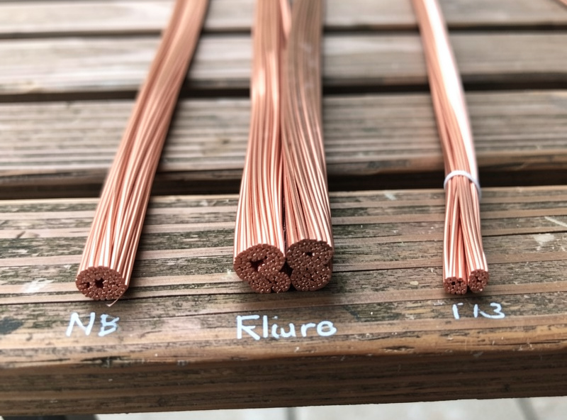
My honest take: for a short welder run I stay in copper because it’s forgiving and the cost difference is small at those lengths. Aluminum wants anti-oxidant compound on the terminations and connectors rated for it, and a loose aluminum lug is a classic slow-cooking failure. This is squarely where I defer — my welder friend Mike, decades in the trade, has re-torqued more sketchy aluminum terminations than I’ve laid beads, and his rule is simple: if you’re mixing aluminum and inexperience, hire it out. Wire makers like Southwire publish the ampacity and de-rating tables if you want to check the numbers yourself.
When Do I Need to Upsize the Wire?
Upsize the conductor whenever the run gets long, because resistance grows with distance and steals voltage the welder needs. The working target electricians use is holding voltage drop under about 3% on a branch circuit; past roughly 50 feet of run, that often means bumping up one wire size even if the ampacity chart says you’re fine.
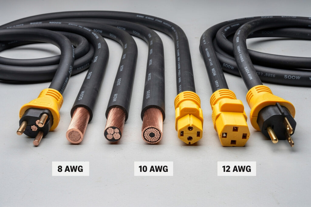
I learned this on the far end of an extension cord, not fixed wiring. I once reached a job across the shop on a long, skinny cord and the arc kept stuttering out on plate — I blamed the machine, the gas, the tip, everything but the cord. The power at the far end had sagged low enough that the inverter couldn’t hold the arc. The fix was a heavy Iron Box cord sized for the run. Same lesson applies to permanent wiring: distance is a load. My full breakdown of cord sizing is in the welding extension cord gauge guide, and it’ll save you the afternoon I lost.
What Happens If I Get It Wrong?
Undersize the wire and it runs hot — the insulation cooks, the terminations loosen, and in the worst case you get a fire inside a wall where you can’t see it coming. Undersize the breaker relative to the machine and you get endless nuisance trips. Oversize the breaker relative to the wire and you remove the very protection that keeps the wire from overheating. None of these announce themselves politely.
The tell I trust is heat and smell: a breaker or receptacle that’s warm to the touch after a welding session, or that faint hot-plastic smell near an outlet, means something is undersized or loose and you stop and investigate. I’ve felt a warm receptacle once, traced it to a marginal connection, and never ignored one since. This is real-stakes territory, not a preference — the welding electrical safety guide covers the shock and ground-fault side, and the broader beginner hazards live in the complete beginner’s guide. When the numbers don’t add up cleanly, that’s not a reason to guess bigger — it’s the moment to bring in a licensed electrician.
What size breaker and wire does a 200-amp welder need?
It depends on input current, not output. A typical 200-amp class 240V MIG or inverter draws roughly 24 to 32 input amps and runs on a 40-amp breaker with 8 AWG copper. A 200 to 250-amp stick or multiprocess machine that draws more may need a 50-amp breaker on 6 AWG. Always confirm against the nameplate.
Can I use 10 AWG wire on a 40-amp welder circuit?
No. Under the small-conductor rule, 10 AWG copper is limited to a 30-amp breaker regardless of its insulation rating. A 40-amp circuit needs 8 AWG copper, and a 50-amp circuit needs 6 AWG. Using 10 AWG on a 40-amp breaker leaves the wire underprotected and prone to overheating.
Why can a welder run on a breaker bigger than its amp draw?
Because a welder is an intermittent load. NEC Article 630 allows the overcurrent device to be sized up to 200 percent of rated input current so the inrush does not nuisance-trip, while the conductor is sized on the duty-cycle-adjusted current. The wire never carries full current long enough to overheat.
Is copper or aluminum wire better for a welder circuit?
Copper is more forgiving and standard for short welder runs. Aluminum costs less and suits long high-current runs, but carries less current per gauge, so you step up about two sizes, and it needs anti-oxidant compound and aluminum-rated terminations. For most home shops, copper is the simpler, safer choice.
Do I need to upsize the wire for a long run to my welder?
Often, yes. Resistance grows with distance, so a long run loses voltage that the welder needs to hold its arc. Electricians target under about 3 percent voltage drop on a branch circuit, which past roughly 50 feet usually means bumping up one wire size even when the basic ampacity chart says you are fine.

Discussion (0)