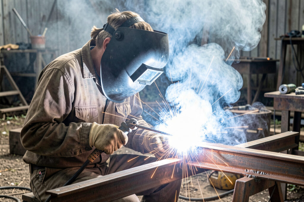
Welding porosity is gas trapped inside the bead during solidification, appearing as surface holes or hidden cavities. Seven main causes: dirty metal, wrong gas flow, drafts, wet wire, painted/galvanized base metal, contaminated tungsten, and gas line leaks.
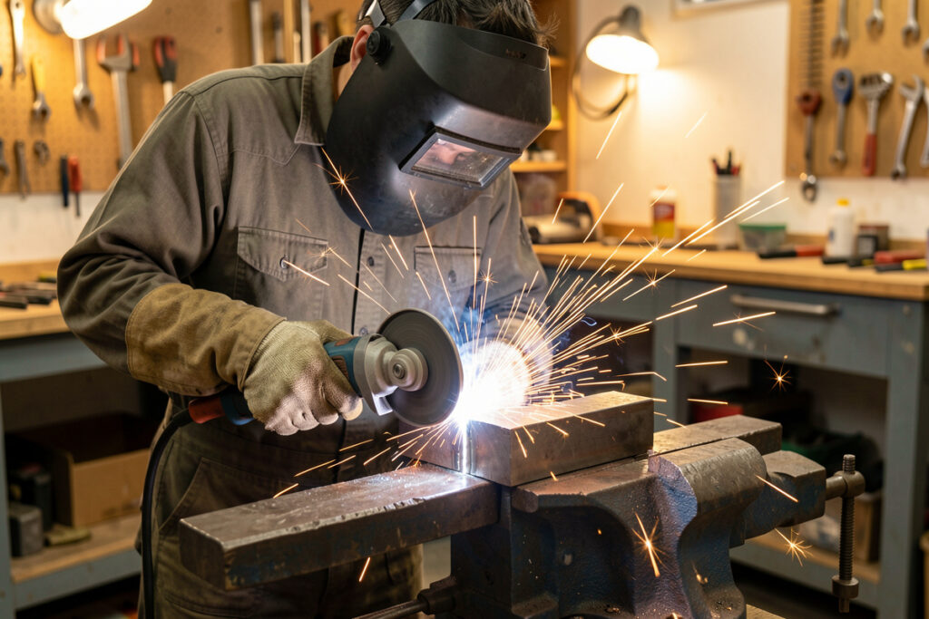
The first welded fence rail I built had pinhole porosity along the bottom 2 inches of every joint. I assumed wrong settings until I noticed my argon cylinder was at 200 PSI instead of 2,400 — the regulator was leaking and I had been welding with one-tenth the gas flow I thought I had. AWS D1.1’s visual acceptance criteria for structural welds set tight, size-based limits on visible piping porosity — strict enough that a few pinhole-looking spots can fail inspection on certified work (AWS D1.1 acceptance-criteria summary) — so cosmetic-looking pinholes are not just cosmetic. The full diagnostic playbook is in the welding troubleshooting guide.
Porosity is the single most common weld defect for home hobbyists, and the one that most consistently fails inspection on any structural project. The good news is that porosity is almost always preventable with surface prep and gas management. The bad news is that even one tiny pinhole indicates the surrounding bead has reduced strength — porosity is never just cosmetic on load-bearing welds.
The Two Types of Porosity and What Each Indicates
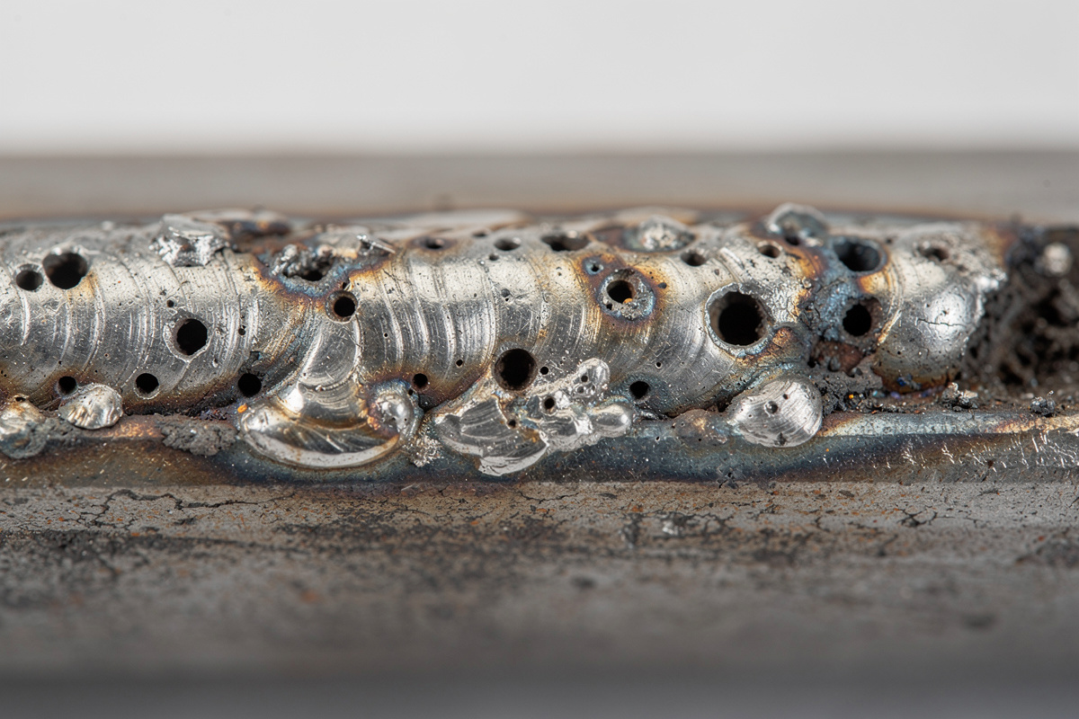
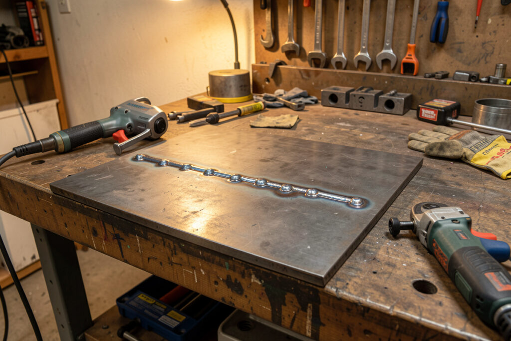
Surface porosity is visible holes or pinpricks on the weld bead exterior; subsurface porosity is hidden cavities only revealed by grinding, X-ray, or destructive testing. Surface porosity tells you the contamination was severe enough to reach the surface as the weld solidified; subsurface porosity means smaller amounts trapped before reaching the top.
Differences in cause and severity:
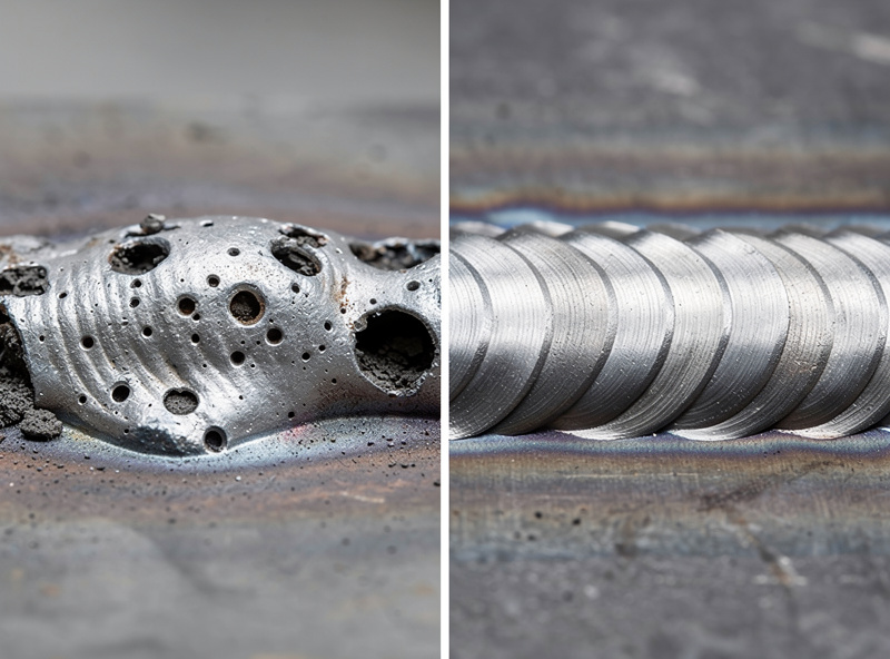
- Surface porosity (visible pinholes): Severe contamination — usually no shielding gas, blowing draft, or heavy oil/paint contamination. Cosmetically obvious; structurally compromised.
- Subsurface porosity (hidden cavities): Moderate contamination that mostly outgassed but trapped some bubbles. Usually only found via grinding or radiography. Reduces strength but the bead looks fine.
- Worm-track porosity (linear cavities): Long elongated holes parallel to weld direction, usually caused by flux-core wire on dirty metal or wrong polarity.
- Cluster porosity (multiple pinholes grouped): Localized contamination, often from a specific point of paint or oil on the joint.
- Distributed porosity (evenly spread pinholes): Systemic problem — gas line leak, contaminated wire, or blanket draft across the entire weld zone.
Cluster porosity often looks like a single bad spot you can repair; distributed porosity means the entire weld is suspect. The repair strategy differs accordingly. For specific MIG troubleshooting, see our guide on why is my MIG weld so spattery.
The Seven Causes of Welding Porosity
Seven causes cover nearly every porosity case I’ve chased down in a home shop: contaminated base metal, no or insufficient shielding gas, drafts disrupting gas coverage, wet or contaminated filler wire, painted or galvanized base metal, contaminated tungsten on TIG, and gas line leaks. Each cause has distinct symptoms that narrow the diagnosis quickly.
Cause-by-cause diagnosis:
- Dirty base metal (oil, rust, mill scale): Surface and subsurface porosity randomly distributed. The most common cause I run into on my own bench and in Mike’s shop, by a wide margin.
- No shielding gas / wrong flow rate: Severe distributed surface porosity. Check cylinder valve open, flowmeter set to 20-25 CFH for MIG, hoses for kinks.
- Drafts (open garage door, fan, AC vent): Worm-track or one-sided porosity facing the draft direction. Bag the work area or shut off the draft.
- Wet or rusty filler wire: Random pinholes consistent across multiple welds. Replace wire or rod and store dry.
- Galvanized or painted base metal: Heavy worm-track porosity with visible smoke and zinc whiskers. Grind the coating off the joint area before welding.
- Contaminated tungsten (TIG only): Localized porosity at the tungsten dip site. Re-grind tungsten 1/4 inch back from the contaminated tip.
- Gas line leaks: Distributed porosity that does not resolve with surface prep. Soap-water test all connections from cylinder to torch.
The diagnostic order matters. Start with surface prep — it clears the biggest chunk of cases by itself — then check gas, then check drafts, then dive into wire and equipment issues. In my own troubleshooting, most home porosity resolves at step 1 or 2 before I ever have to touch the machine. Read more on inspection tools in our best budget welder under 300 dollars guide.
Surface Preparation: The Most Important Step
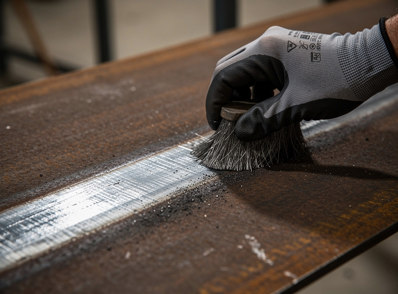
Wire-brush, grind, or sandblast the joint area to bright metal before welding. Mill scale, rust, paint, oil, and zinc plating all release gas during welding that gets trapped in the solidifying bead. Cleaning extends 1/2 inch beyond the actual joint to prevent edge contamination flowing into the puddle.
Surface prep procedures by contamination type:
- Mill scale (blue-black coating on hot-rolled steel): Wire-brush with an angle grinder; flap disc works faster but takes more material. Aim for bright bare metal.
- Rust (red-brown surface): Wire-brush light rust, grind heavy rust. Pitted rust requires going down to clean metal beneath the pits.
- Paint: Grind off completely 1/2 inch around the joint. Paint thinner softens it but does not remove enough for clean welds.
- Oil and grease: Wipe with mineral spirits or acetone, then dry completely before welding. Trapped solvent vapors contribute to porosity.
- Zinc galvanizing: Grind off the zinc layer entirely from the joint area. Zinc fumes are toxic AND cause severe porosity.
- Cutting fluid residue: Wipe with acetone after machining/cutting. Cutting fluid traces are common porosity causes after CNC or saw cuts.
The “1/2 inch beyond the joint” rule prevents weld puddle drift from reaching contaminated edges. Some welders skip this and grind only the visible joint surface; the result is porosity at the toe of the weld where the puddle reached the edge of the cleaned area. Read about coated metal hazards in our guide on welding ventilation requirements for home garage.
Shielding Gas Settings and Common Failures
Set MIG shielding gas flow to 20-25 cubic feet per hour (CFH) for indoor work, 25-30 CFH for outdoor or drafty conditions. TIG flow runs lower at 15-20 CFH for steel, 20-25 CFH for aluminum. Too low produces porosity from inadequate coverage; too high produces porosity from turbulent flow that pulls in atmosphere — that second failure mode trips up a lot of beginners who assume more gas can only help (gas-flow mechanism explained).
Gas-related failure modes:
- No gas flowing at all: Cylinder valve closed, flowmeter at zero, or hose disconnected. Check first whenever porosity appears suddenly.
- Flow too low (under 15 CFH): Insufficient shielding coverage. Bump up to 20 CFH minimum.
- Flow too high (over 35 CFH): Turbulent flow pulls atmosphere into the gas envelope. Counter-intuitive but real cause.
- Gas line leak: Air gets pulled into the line and reaches the torch. Soap-water test reveals bubbles at any failed fitting.
- Wrong gas mix: Pure CO2 on stainless, pure argon on steel — wrong gas produces porosity and bad welds. Match gas to metal and process.
- Empty cylinder: Pressure drops below 100 PSI and flow becomes erratic. Most regulators show inlet pressure; below 100 PSI = refill time.
- Gas diffuser blocked with spatter: The disc inside the gun nozzle clogs over time. Clean monthly with a contact-tip drill bit or replace.
Soap-water leak testing is the underrated diagnostic. Mix a few drops of dish soap in water, paint it on every gas connection from regulator to torch, watch for bubbles. The test takes 60 seconds and finds leaks no other test catches. For more on gas mix selection, see our MIG welding settings chart.
Equipment-Related Porosity Causes
Three equipment issues regularly cause porosity even with perfect surface prep and gas: contaminated MIG nozzle (spatter blocks gas flow), worn O-rings on gun cable connections (atmospheric leak), and a torn liner inside the MIG gun cable (wire feeds with gaps that pull atmosphere). Each shows up as inconsistent porosity that resists other fixes.
Equipment fixes:
- Spatter-clogged MIG nozzle: Knock spatter free with MIG pliers. If diffuser holes are blocked, replace the nozzle. Dip new nozzles in anti-spatter spray every shift.
- Worn cable O-rings: Replace the O-rings on gun-to-machine connections every 6-12 months. They are 2-3 dollars and atmospheric leaks at this point are common.
- Torn MIG liner: The plastic or metal liner inside the gun cable wears at the curve. A torn liner drops wire feed reliability AND lets atmosphere into the gas envelope. Replace every 2-3 years on hobby use.
- Loose contact tip: A finger-tight tip lets gas leak at the threads. Snug to gun pliers tight.
- Damaged regulator: A frozen or sticking regulator delivers erratic flow. Test with a flowmeter; replace if flow varies more than 5% under steady conditions.
- Leaking flow meter calibration: A flowmeter ball that bounces during welding indicates pressure pulsing. Internal seal problem; usually requires regulator replacement.
Equipment causes are the second-most-frustrating after drafts because they show up after multiple sessions of “perfect” prep that suddenly produces porosity. The diagnostic test is to compare welds in identical conditions on the same metal — if porosity appears on one machine but not on a known-good machine, the equipment is the issue.
How to Repair Porous Welds
Repair porous welds by grinding out the defective material to clean metal, then re-welding with proper surface prep and parameters. Single pinholes can be drilled out with a 1/8-inch bit and re-welded as a plug; cluster porosity needs a 1/4-inch grind-out and a multi-pass repair. Distributed porosity along the entire bead means re-doing the joint from scratch.
The repair workflow:
- Identify the porous area extent. Single pinhole vs cluster vs distributed — three different repair scopes.
- Grind out the defect plus 1/4 inch margin. Use an angle grinder with a 4.5-inch flap disc or a die grinder for tight spaces.
- Inspect the cavity bottom. Grind until you see clean parent metal — no rust, no oil, no remnant porosity.
- Clean the surrounding 1/2 inch area. Wire-brush to bright metal.
- Re-weld with corrected parameters. If you found the cause (gas, draft, prep), this prevents repeat.
- Inspect the repair under bright light. Surface porosity is visible; cluster porosity may need dye-penetrant testing.
- Document the cause and fix in your log. Notes prevent repeat in future projects.
The cost of repair is usually the metal you grind out plus the time. Repair on structural welds requires re-inspection if certified work is involved; on hobby welds, visual inspection suffices. The reliable habit is to fix the cause before repairing the symptom — re-welding without addressing what caused porosity produces porous welds again. Read about specific weld inspection in our guide on MIG weld spattery causes.
Frequently Asked Questions
What causes porosity in MIG welding?
The most common causes are contaminated base metal (rust, mill scale, paint, oil), no shielding gas or wrong flow rate, drafts blowing the gas away, and wet wire or contaminated nozzle. Most home-shop porosity resolves once surface prep and gas flow (20-25 CFH) are both dialed in correctly.
Can I weld over rust without porosity?
No. Rust contains water and oxygen that gas off when heated, both of which cause porosity. Even light rust requires wire-brushing to bright metal before welding. Heavy rust requires grinding because the underlying metal is pitted and contaminated.
Why does my weld have porosity outdoors but not in the garage?
Wind. A 5-mph breeze pulls shielding gas away from the weld puddle and lets atmosphere reach the molten metal. Block the wind with a windbreak, set up indoors, or increase gas flow to 30-35 CFH and accept higher gas consumption.
Does flux-core MIG produce more porosity than gas-shielded MIG?
Generally no — flux-core produces shielding gas internally and tolerates outdoor conditions better. But flux-core is more sensitive to dirty base metal and produces worm-track porosity with painted or galvanized steel. Surface prep is even more critical with flux-core.
Can I fix porosity by turning up the heat?
No. Higher heat input does not eliminate the underlying contamination cause. It may slightly improve the look of porous welds by giving more time for gas to escape, but the underlying weakness remains. Always fix the contamination cause before changing parameters.
How much porosity is acceptable in a hobby weld?
For non-structural decorative or fab welds, scattered pinholes may be cosmetically acceptable. For any load-bearing application — chairs, tables, racks, fences — porosity reduces strength noticeably and should be ground out and re-welded. Aim for zero visible porosity on structural work.
Discussion (0)