Welding defects follow predictable patterns with specific causes and fixes. Porosity comes from gas contamination, spatter from incorrect voltage or dirty metal, burn-through from excess heat, and cracking from improper cooling. This guide identifies each defect and provides the exact fix.
I have ground out and re-welded every defect on this page at least once — porosity from a half-empty argon bottle that I assumed was fine, undercut from running too hot on 16-gauge sheet, cold lap from too-cold settings on a galvanized fence rail, transverse cracks on a quench-cooled fillet I tried to dunk in water to speed up. Every one of them has a signature: porosity sounds different (pop-pop-pop instead of frying-bacon hiss), undercut leaves a finger-felt groove at the weld toe, cold lap looks like a bead sitting on top instead of fused. The diagnostic trick is reading those signatures fast so you fix the cause once instead of regrinding three times. For first-time-welder context, see welding for beginners; for the MIG-process foundation, see MIG welding complete guide and TIG welding guide.
Every welder — from beginner to professional — encounters defects. The difference is how quickly you identify the cause and apply the correct fix. A beginner who sees porosity might grind out the weld and re-weld with the same settings, producing the same porosity. An experienced welder recognizes porosity patterns, checks gas flow, base metal cleanliness, and wind conditions, fixes the root cause once, and produces a sound weld on the next pass.
Weld Defect Identification
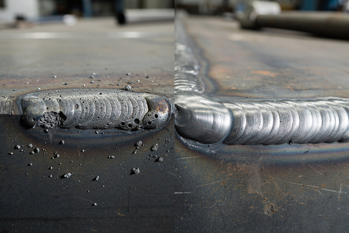
Before you can fix a defect, you must correctly identify it. Weld defects have distinct visual signatures that point to specific causes. Learn to read the weld bead — its shape, color, surface texture, and toe fusion tell you exactly what went wrong.
Porosity appears as visible bubbles, pinholes, or sponge-like surfaces in the weld bead. External porosity is visible on the surface. Internal porosity requires X-ray or ultrasonic testing to detect — visual inspection only catches surface-breaking pores — but for home projects, surface inspection is still the practical first check since most home-shop porosity shows itself at the surface. Porosity concentrates in clusters rather than evenly distributed, which is also why quality standards apply tighter limits to clustered porosity than to a single isolated pore — if you see one pinhole, grind back 1 inch and you will likely find more.
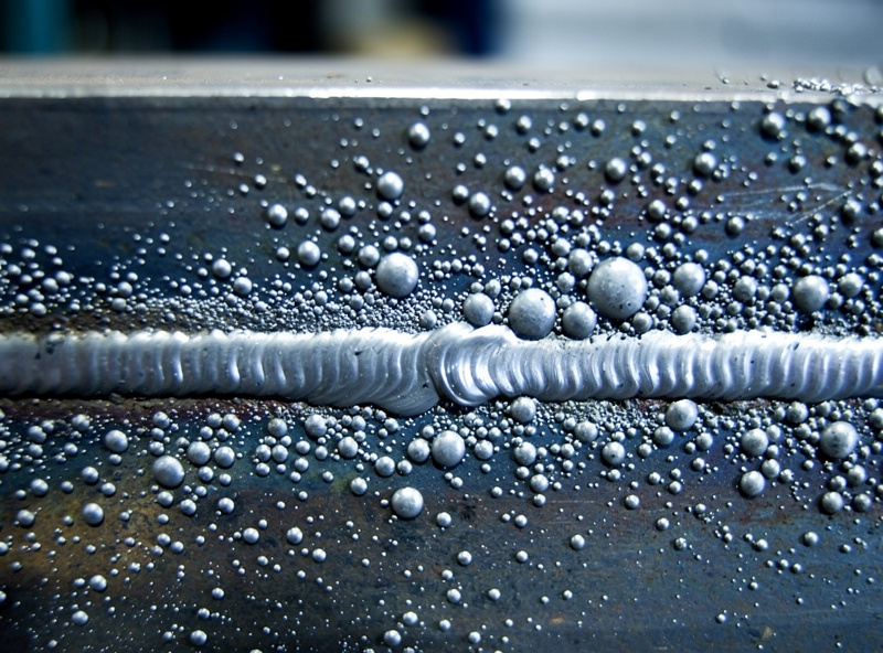
Spatter consists of small metal balls adhered to the base metal around the weld bead. Some spatter is normal on MIG and Stick welding — excessive spatter indicates a settings or technique problem. Spatter ball size and distribution patterns help diagnose the cause: large balls close to the weld indicate low voltage, small balls scattered widely indicate long stick-out or dirty metal.
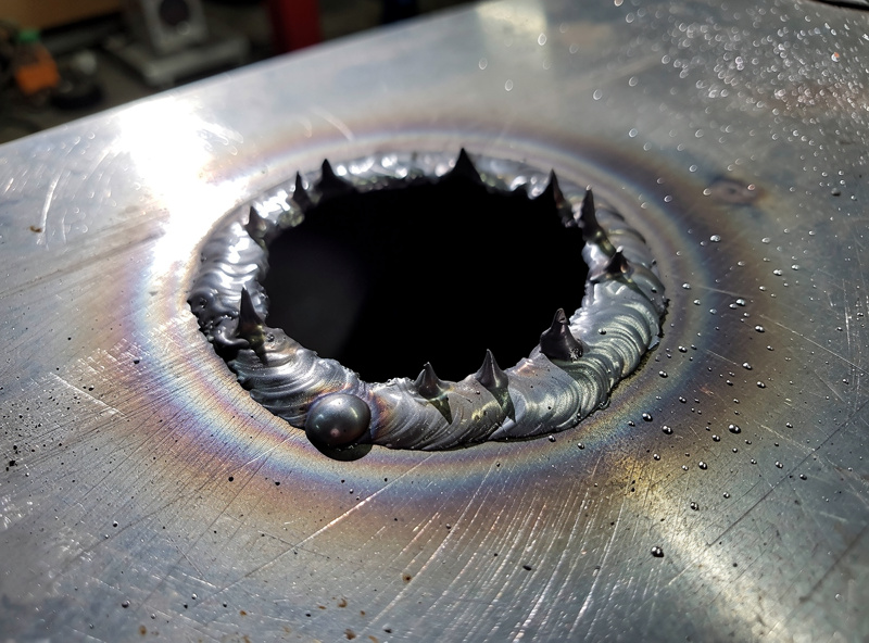
Burn-through is a hole melted completely through the base metal. It indicates heat input exceeding the thermal capacity of the material. Burn-through is most common on 20-gauge and thinner material, corner joints where heat concentrates, and at the end of beads where you pause. On butt joints, burn-through leaves a ragged hole. On fillet welds, it appears as a sagging or dropping of the weld metal through the joint root.
Lack of fusion appears as a visible seam or groove where the weld bead meets the base metal. The bead sits on top of the metal without melting into it. Running your fingernail along the toe of the weld catches on the seam. Lack of fusion produces a weld that looks acceptable but can be peeled apart with a chisel because the filler metal never bonded to the base metal. It is the most dangerous defect because it is invisible in a casual visual inspection.
Cracking appears as visible lines in or adjacent to the weld bead. Hot cracks form during solidification and appear as jagged lines in the center of the bead. Cold cracks (hydrogen-induced) appear hours or days after welding as straight lines in the heat-affected zone. Any crack in a structural weld is a reject — grind it out completely and re-weld. Cracks propagate under load and cause catastrophic joint failure. The weld cracking causes and prevention guide covers the specific causes of hot cracking versus cold cracking, which metals are highest risk, and the preheat and filler choices that eliminate cracking from the root of the problem.
Porosity: Causes and Fixes
Porosity results from gas trapped in the solidifying weld metal. The gas source can be atmospheric contamination, base metal contamination, or shielding gas issues. Identifying which gas is trapped and where it came from determines the fix.
The most common cause of MIG porosity is insufficient shielding gas coverage. Check your flow rate — 20-25 CFH for most MIG work. If the bottle gauge reads below 200 PSI, the regulator may be starved and delivering inconsistent flow. Replace or refill the bottle. Clean spatter from the nozzle and check that the gas diffuser (inside the nozzle) is not clogged. A nozzle half-full of spatter restricts gas flow and creates turbulence that pulls atmospheric air into the arc zone.
Contaminated base metal is the second most common cause. Oil, grease, paint, rust, zinc (galvanized coating), and cutting fluid all release gases when heated by the arc. Wipe the joint area with acetone on a clean rag. Grind the weld zone to bright metal on both sides of the joint. For galvanized steel, grind the zinc coating off for at least 1/4 inch on each side of the joint. In my own shop, cleaning to bright metal before every joint has cut porosity complaints down to almost nothing — it is the single highest-yield prep step I do.
Wind blowing shielding gas away from the arc causes porosity on outdoor welds. Even a 5 mph breeze disrupts gas coverage. Weld inside a windscreen (cardboard box works) or switch to flux-cored wire for outdoor work. The welding porosity guide covers all causes with specific detection methods and fixes for MIG, TIG, and Stick welding.
Spatter: Causes and Fixes
Spatter is molten metal ejected from the arc that solidifies on the base metal surface. While some spatter is unavoidable in MIG and Stick welding, excessive spatter wastes wire, creates cleanup work, and indicates settings that produce poor weld quality.
Low voltage for your wire speed is the number one cause of MIG spatter. When voltage is too low, the arc does not melt the wire smoothly into the puddle — instead, the wire stubs into the puddle and explodes, ejecting molten metal outward. Increase voltage one click at a time until spatter reduces. The correct voltage produces a smooth, sizzling arc sound (not popping or crackling).
Long stick-out (over 3/4 inch) reduces the effective voltage at the arc because the wire resistance consumes more voltage as it heats on the way to the workpiece. Shorten stick-out to 1/2 inch for maximum penetration and minimum spatter, or 5/8 inch for thin metal where reduced heat helps.
Wrong polarity causes severe spatter. Solid wire MIG requires DCEP (electrode positive). Flux-cored wire is where welders get tripped up because the correct polarity depends on which flux-cored wire you’re running: self-shielded gasless wire (E71T-GS, E71T-11) runs DCEN (electrode negative), while gas-shielded flux-cored wire (E71T-1) runs DCEP like solid wire — check the spool’s own data sheet rather than assuming, since running the wrong polarity for that specific wire causes poor penetration, excessive spatter, and an unstable arc. If you switched wire types but forgot to swap the polarity connector, your welds will be covered in spatter and porosity. The MIG spatter troubleshooting guide covers all 10 common causes with exact fixes for each.
Anti-spatter spray ($5-10 per can) applied to the base metal before welding prevents spatter from adhering. Spray the area around the joint, not the joint itself — anti-spatter on the joint surface can contaminate the weld. After welding, spatter balls treated with anti-spatter spray pop off with a light brush or tap instead of requiring grinding.
Burn-Through: Causes and Fixes
Burn-through occurs when the arc melts through the full thickness of the base metal. It is the most common defect on thin material (20-gauge and thinner) and at heat-concentrating joint geometries like corners and end-of-bead locations.
Excessive amperage or voltage is the primary cause. On a MIG welder, reduce voltage one click or increase travel speed to reduce heat input per inch of weld. On a TIG welder, reduce foot pedal pressure or lower the maximum amperage setting. For 16-gauge mild steel MIG, 17-18 volts is the sweet spot. Going above 19 volts on 16-gauge increases burn-through risk significantly.
Slow travel speed deposits more heat per inch than the base metal can absorb. Beginners often weld too slowly because they are trying to maintain control. Practice increasing travel speed on scrap until you find the fastest speed that still produces a sound bead. On 16-gauge, a travel speed of 15-20 inches per minute for MIG prevents burn-through while maintaining penetration.
Joint geometry concentrates heat at corners and at the end of beads. On corner joints, weld in short 1-2 inch segments with cooling time between each segment (stitch welding). At the end of a bead where burn-through often occurs, taper off your amperage (TIG foot pedal) or whip the MIG gun forward and back to distribute heat over a wider area as you finish.
Heat sinks clamped behind the joint absorb excess heat and prevent burn-through on thin material. A copper or aluminum block placed behind the joint conducts heat away from the weld zone. This technique is standard practice when TIG welding stainless exhaust tubing (16-18 gauge) where burn-through is the primary failure mode. The MIG burn-through and wire problems guide covers settings-related burn-through causes specific to MIG welding.
Lack of Fusion: Causes and Fixes
Lack of fusion is the most dangerous weld defect because the weld looks acceptable but has near-zero strength. The filler metal sits on top of the base metal without melting into it. A fusion-deficient weld passes casual inspection but fails catastrophically under load.
Insufficient heat input causes lack of fusion. The arc does not melt the base metal surface before the filler metal solidifies over it. On MIG, increase voltage one click. On TIG, increase amperage or slow travel speed. On Stick, use a larger diameter electrode or increase amperage. The puddle must wet into the base metal — if the bead sits on top like a worm, you lack fusion.
Improper work angle directs the arc away from one side of the joint. On a T-joint, both legs of the fillet must receive equal heat. Aim the arc at the corner of the T, not the flat plate or the vertical plate. On a butt joint, angle the torch 5-10 degrees toward the trailing edge of the puddle to maintain fusion at both edges. Freehand inconsistency is the most common angle error — use a brace or drag technique to maintain consistent angle.
Contamination at the joint interface prevents fusion even at correct settings. Mill scale, rust, and paint between faying surfaces (the surfaces that touch each other in the joint) prevent metal-to-metal contact. Clean both surfaces before fit-up — not just the visible face. On lap joints and T-joints where faying surfaces are hidden, grind or wire brush both mating surfaces before assembly. The complete lack-of-fusion diagnostic — including how to detect it with a chisel test on finished welds and the process-specific heat corrections for MIG, TIG, and Stick — is in the lack of fusion welding fix guide.
Cracking: Causes and Fixes
Cracks are the most serious weld defect. They propagate under load and cause sudden, catastrophic joint failure. Any crack — regardless of size — requires complete removal and re-welding. Understanding crack causes prevents them from occurring.
Hot cracks form during weld metal solidification when the alloy composition creates a wide solidification range. Sulfur and phosphorus in the base metal expand this range and increase hot crack risk. Use low-sulfur base metal (most structural steel qualifies) and matching filler wire. On long beads, weld from the center outward in both directions rather than from one end to the other — this allows shrinkage stresses to distribute evenly.
Cold cracks (hydrogen-induced cracking) form hours or days after welding when hydrogen trapped in the weld metal or heat-affected zone diffuses to stress concentration points and initiates cracking. Prevention: use low-hydrogen electrodes (E7018 for Stick, or fresh dry wire for MIG), pre-heat thick sections (over 1 inch) to 200-300°F, and slow-cool the welded piece by covering it with a welding blanket. Grinding a weld smooth removes the surface where hydrogen escapes — leave structural welds as-welded unless appearance is critical.
Restraint cracking occurs when the welded assembly cannot shrink freely as the weld cools. Heavy clamping, tack welds that are too large, and welding in sequence that traps shrinkage all cause restraint cracks. Tack with small 1/4-inch tacks, weld in balanced sequences (opposite sides, alternating ends), and allow the assembly to move during cooling. On long continuous welds, skip-weld in alternating segments to distribute shrinkage.
Weld Defect Comparison Table
| Defect | Visual Sign | Primary Causes | Fix | Severity |
|---|---|---|---|---|
| Porosity | Bubbles, pinholes, sponge surface | Low gas flow, dirty metal, wind | Check gas, clean metal, block wind | Medium — weakens cross-section |
| Spatter | Metal balls on base metal | Low voltage, long stick-out, dirty metal | Increase voltage, shorten stick-out, clean | Low — cosmetic issue |
| Burn-Through | Hole through base metal | Too much heat, slow travel, thin material | Reduce voltage, speed up, heat sink | High — structural failure point |
| Lack of Fusion | Visible seam at weld toe | Low heat, wrong angle, contamination | Increase heat, correct angle, clean | Critical — zero joint strength |
| Undercut | Groove at weld toe | Too fast, too much voltage, wrong angle | Slow down, reduce voltage, adjust angle | Medium — reduces cross-section |
| Hot Crack | Jagged line in bead center | High sulfur, rapid cooling, restraint | Use correct filler, balanced weld sequence | Critical — propagates under load |
| Cold Crack | Straight line in HAZ, hours later | Hydrogen, thick sections, rapid cooling | Low-H consumables, pre-heat, slow cool | Critical — delayed failure |
| Incomplete Penetration | Root side not fused | Too little heat, gap too tight, too fast | Increase heat, open root gap, slow down | High — partial joint strength |
Use this table as a diagnostic reference. When you see a defect, match its visual appearance to the first column, read across to identify the likely cause, and apply the listed fix. If the defect persists after the first fix attempt, move to the next cause in the list. Most defects have one primary cause and one or two secondary causes — address the primary cause first. For a dedicated deep-dive on the groove at the weld toe — measuring acceptable limits, the voltage and travel-speed causes, and the specific fix sequence — see the welding undercut causes and fix guide.
Systematic Troubleshooting Process
When a weld looks wrong, resist the urge to change multiple settings at once. Follow this three-step diagnostic process to isolate the root cause efficiently.
Step one: identify the defect from its visual appearance. Is it porosity, spatter, burn-through, lack of fusion, or cracking? Each defect points to a specific category of causes.
Step two: check the three most common causes for that defect category. For porosity: gas flow, base metal cleanliness, wind. For spatter: voltage, stick-out, polarity. For burn-through: heat input, travel speed, material thickness. For lack of fusion: heat, angle, contamination. Fix the most likely cause first.
Step three: test on scrap before continuing on your project. Lay a 2-inch bead on scrap metal of the same thickness. Examine the test bead. If the defect is gone, continue welding your project. If the defect persists, return to step two and try the next likely cause. This 2-minute test prevents wasting material on your actual project while troubleshooting.
Document your fixes. When you solve a recurring problem, write down the settings, the cause, and the fix. A troubleshooting journal (even a sticky note on your welder) builds a personal reference that eliminates repeat diagnosis. After 6 months of welding, your journal will cover 90 percent of the problems you encounter.
Frequently Asked Questions
Why does my MIG weld have bubbles in it?
Bubbles (porosity) in a MIG weld come from trapped gas caused by insufficient shielding gas flow, contaminated base metal, or wind blowing gas away from the arc. Check your gas flow rate is 20-25 CFH, clean the weld zone to bright metal, and block wind if welding outdoors. A clogged nozzle from spatter buildup also restricts gas flow.
How do I fix a porous weld?
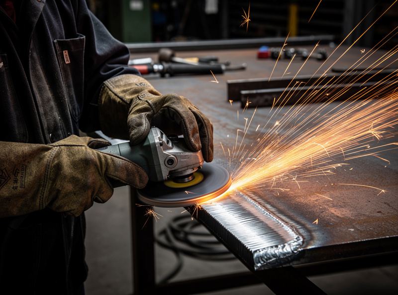
Grind out the porous section until you reach solid metal — do not weld over porosity because the trapped gas expands and creates more porosity. Identify and fix the root cause (gas flow, contamination, wind) before re-welding. Re-weld using correct settings on cleaned metal with verified gas flow. Check the repair bead for soundness before moving on.
What causes burn-through on thin metal?
Burn-through on thin metal (20-gauge and thinner) comes from too much heat input. Reduce voltage, increase travel speed, or use a stitch welding pattern instead of a continuous bead. On MIG, try 17-18 volts on 16-gauge steel. On TIG, reduce amperage or use pulse mode. Clamp a copper or aluminum heat sink behind the joint to absorb excess heat.
Why does my MIG weld have so much spatter?
Excessive MIG spatter usually means voltage is too low for your wire speed, stick-out is longer than 3/4 inch, or polarity is set wrong. Solid wire requires DCEP (electrode positive). Increase voltage one click, shorten stick-out to 1/2 inch, and verify polarity. Dirty base metal also produces spatter — clean the joint to bright metal.
How can I tell if my weld has good fusion?
A well-fused weld has smooth transition at both toes (edges) where the bead meets the base metal — no visible seam or groove. Run your fingernail along the weld toe: if it catches on a groove, you have lack of fusion. The bead should be slightly concave to flat, not sitting on top of the metal like a rope. Complete penetration shows a uniform bead on the back side of a butt joint.
Can I weld over a crack to fix it?
Never weld over a crack. The crack propagates through the new weld because the root cause (restraint, hydrogen, improper cooling) is still present. Grind out the entire crack until you see solid metal with no visible crack lines. Then fix the root cause before re-welding. For hydrogen-induced cracks, pre-heat the area to 200-300°F before re-welding.
Why do my welds crack after they cool?
Cracks that appear hours after welding are hydrogen-induced cold cracks. Prevention: use fresh, dry wire or low-hydrogen electrodes, pre-heat thick sections (over 1 inch) to 200-300°F, and slow-cool by covering with a welding blanket. Avoid grinding structural welds smooth, which traps hydrogen by sealing the escape path through the bead surface.
The Diagnostic Habit That Saves Hours
Before you grind out a defective weld, look at it for 10 seconds and listen to your memory of how the bead sounded going down. Most defects diagnose themselves if you separate the symptom (porosity, spatter, undercut, cold lap, crack) from the technique observation (steady hiss vs popping vs sputtering, gun angle, travel speed, stick-out length). The single highest-yield habit I built was writing the symptom + suspected cause on a piece of soapstone next to the weld before regrinding — by the third weld I had recognized my pattern (always too-long stick-out under fatigue) and fixed the technique once instead of regrinding ten times.
Related Articles
- Welding Porosity: Causes and Fixes
- MIG Weld Spatter: 10 Causes and Fixes
- MIG Welder Burning Through Wire: 8 Causes
- Welding Burns First Aid
- MIG Welding Settings Chart
- MIG Welding Complete Guide
- TIG Welding Guide
- Welding for Beginners
- Essential Welding Equipment Guide
- Welding Safety Guide
- Welding Ventilation for Home Garage
- How to Identify Mystery Steel
- Plasma Cutting and Metal Prep Guide
- Welding Consumables Guide
- DIY Welding Projects Guide
Discussion (0)