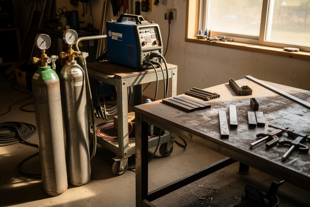
MIG voltage and wire-speed settings track metal thickness and shielding gas. For mild steel with 75/25 argon-CO2 and 0.030 ER70S-6 wire (per AWS A5.18), the rule is 1 amp per 0.001 inch of thickness — 1/8″ needs 18-20V at 250-300 IPM, 1/4″ needs 22-24V at 350-400 IPM.
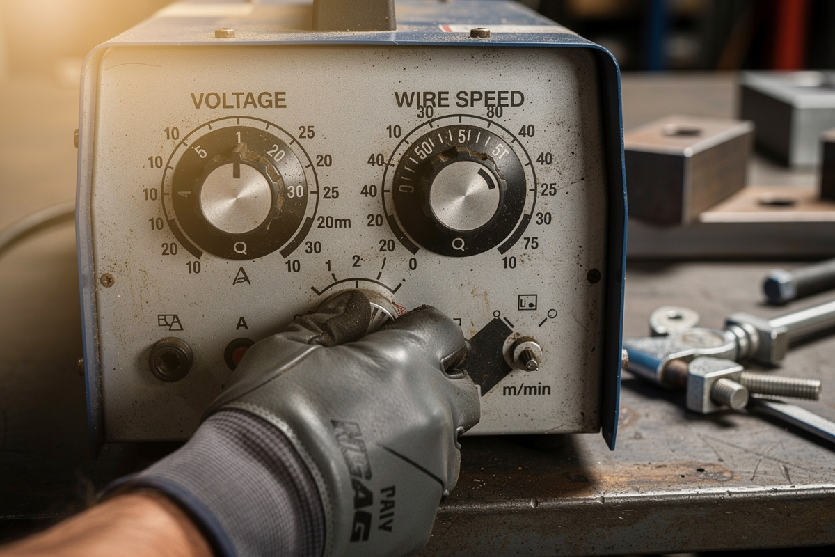
The settings chart on the inside of my Hobart’s door got me through hour one. By hour 50 I was running 0.030 wire on 14-gauge sheet that the chart did not list, with 100% CO2 instead of C25 because my supplier was out of mix, and the chart was useless. The real settings live in the puddle: listen for the steady frying-bacon hiss, watch the bead profile, dial up voltage one click when the bead piles instead of spreading. This guide is the table I built across 80 home projects to fill in the gaps the door chart leaves. For the broader MIG fundamentals, see the MIG welding complete guide.
Most MIG welders ship with a settings chart printed inside the door. Those charts are starting points only — they assume perfectly clean metal, ideal joint geometry, and 75/25 gas. In real home welding, gas mix changes, wire diameter changes, joint type changes, and ambient temperature changes all push the optimum off the printed numbers by 10-30%. The full settings table below covers the variables most door-charts skip.
Why Voltage and Wire Speed Both Matter
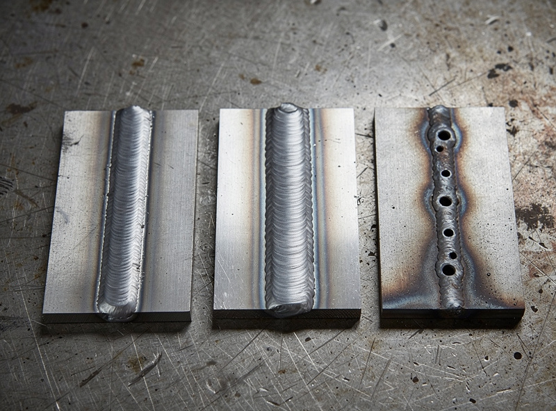
Voltage controls arc length and bead profile (flat vs domed); wire speed controls amperage and penetration depth. Get voltage right and the bead lays flat with even ripples. Get wire speed right and the metal melts to the depth needed without burning through. They are independent variables you tune separately, and getting both right is what separates clean welds from spattery messes. One fast read to bookmark: the weld color chart and meaning guide decodes what each bead color tells you about heat, contamination, and shielding gas coverage — you can diagnose most MIG problems from the color alone before you touch a setting.
The behavior of each control:
- Voltage too low: Bead piles up high and narrow with poor fusion, arc sounds like rapid popcorn.
- Voltage too high: Bead spreads flat and wide, more spatter, undercut at toes. See the welding undercut causes and fix guide for the exact voltage thresholds and repair steps.
- Wire speed too low: Arc stutters and crackles, weld looks under-filled, lack of fusion.
- Wire speed too high: Wire pushes against the metal before melting, “stubbing” or “stuttering” feedback through the gun.
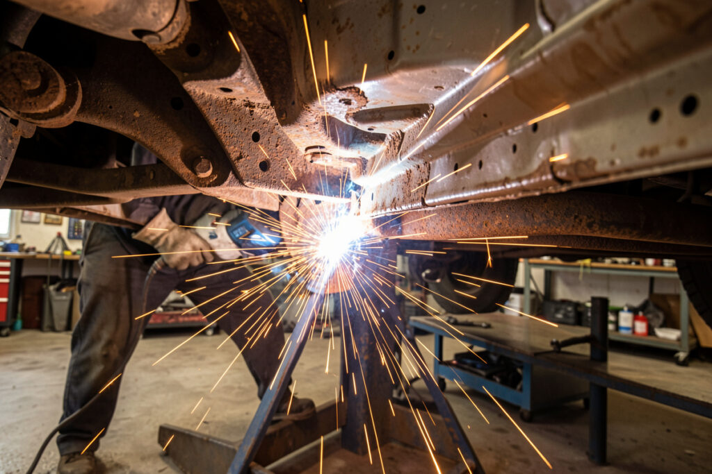
- Both correct: Even sizzling sound like bacon, smooth bead with consistent ripples, minimal spatter.
The bacon-sizzle audible test is the most reliable real-time check. Recordings of professionals welding the same joint have measurably similar acoustic signatures regardless of brand of welder. Read about specific MIG troubleshooting in our guide on why is my MIG weld so spattery.
Settings Chart for Mild Steel (Most Common Hobbyist Use)
This chart assumes 75/25 argon-CO2 shielding gas at 20-25 cubic feet per hour, ER70S-6 solid wire, and clean mill-scale-free steel. Ranges given accommodate brand differences between Lincoln, Miller, Hobart, ESAB, and Forney. For galvanized, painted, or rusty steel, expect to drop voltage 1-2 volts to compensate.
| Steel Thickness | Wire Diameter | Voltage | Wire Speed (IPM) | Approx. Amps |
|---|---|---|---|---|
| 22 gauge (0.030 in) | 0.023 in | 14-16 V | 120-160 | 30-50 |
| 20 gauge (0.036 in) | 0.023 in | 15-17 V | 140-180 | 40-60 |
| 18 gauge (0.048 in) | 0.023 / 0.030 in | 16-18 V | 160-220 | 50-80 |
| 16 gauge (0.060 in) | 0.030 in | 17-19 V | 200-260 | 70-110 |
| 14 gauge (0.075 in) | 0.030 in | 18-20 V | 240-290 | 90-130 |
| 1/8 in (0.125 in) | 0.030 in | 18-20 V | 250-310 | 110-140 |
| 3/16 in (0.188 in) | 0.035 in | 20-22 V | 280-360 | 140-180 |
| 1/4 in (0.250 in) | 0.035 in | 22-24 V | 350-410 | 170-210 |
| 5/16 in (0.313 in) | 0.035 / 0.045 in | 23-26 V | 400-475 | 200-240 |
| 3/8 in (0.375 in) | 0.045 in | 24-27 V | 440-525 | 230-270 |
| 1/2 in (0.500 in) | 0.045 in (multi-pass) | 26-28 V | 500-575 | 260-300 |
The 1-amp-per-0.001-inch rule of thumb tracks within the table — 1/8-inch (125 thousandths) maps to 110-140 amps, 1/4-inch (250 thousandths) maps to 170-210 amps. The rule is a sanity check, not a substitute for the full table.
Adjustments for Different Shielding Gases
Gas mix changes the heat input and arc characteristics. Pure CO2 runs hotter and noisier than 75/25; tri-mix (helium-argon-CO2) runs cooler and quieter. Pure argon is for aluminum only — never on steel. Adjust voltage 1-3 volts based on gas mix while leaving wire speed roughly the same.
Voltage adjustments by gas:
- 75/25 argon-CO2 (standard): Use chart values directly. The hobbyist baseline.
- 90/10 argon-CO2 (cleaner welds): Drop voltage 1 volt, increase wire speed 5-10%. Less spatter, slightly higher cost per cubic foot.
- 100% CO2 (cheapest gas): Add 1-2 volts to chart values. More spatter and a louder, more aggressive arc but acceptable on thicker mild steel.
- Tri-mix (helium-argon-CO2): Drop voltage 2-3 volts. Used mostly for stainless steel; rare in hobby work.
- Pure argon: Aluminum only. On steel, the arc lacks the carbon-monoxide cleaning action and produces porous welds.
- Flux-core (no gas): Different chart entirely; flux-core wire produces shielding gas internally. Voltage runs 1-2 volts lower than gas-shielded MIG.
The single most common gas-related mistake in home welding is using 100% CO2 on thin sheet metal — the extra heat causes burn-through that 75/25 prevents. The second most common is running flux-core wire with shielding gas, which interferes with the wire’s internal flux and produces dirty welds.
Adjustments for Stainless Steel and Aluminum
Stainless steel uses ER308L or ER316L wire with a 90% helium / 7.5% argon / 2.5% CO2 tri-mix shielding gas — helium is the majority gas here, not argon, because its higher thermal conductivity pulls heat away from the weld zone for better fusion with less total heat input; voltage runs 2-3 volts lower than mild steel chart values for the same thickness. Aluminum uses ER4043 or ER5356 wire with pure argon and a spool gun; voltage and wire speed both run 20-30% higher than steel for the same thickness.
Stainless steel settings (per metal thickness):
- 16 gauge stainless: 0.030 wire, 16-18 V, 220-260 IPM.
- 1/8 inch stainless: 0.030 wire, 17-19 V, 260-310 IPM.
- 1/4 inch stainless: 0.035 wire, 20-22 V, 340-400 IPM.
- 3/8 inch stainless: 0.045 wire, 22-25 V, 430-510 IPM.
Aluminum settings (per metal thickness, requires spool gun for reliable feeding):
- 1/16 inch aluminum: 0.030 wire, 16-18 V, 250-300 IPM.
- 1/8 inch aluminum: 0.035 wire, 18-21 V, 340-410 IPM.
- 1/4 inch aluminum: 0.035 wire, 22-25 V, 450-540 IPM.
- 3/8 inch aluminum: 0.045 wire, 25-28 V, 540-630 IPM (multi-pass usually required).
Aluminum MIG without a spool gun is unreliable for hobby welders — the soft wire bird-nests at the drive rolls in standard gun feed. A spool gun adds 200-450 dollars to the welder cost but is the only reasonable path to home aluminum MIG welding. Read about TIG alternatives for aluminum in our piece on tungsten electrode color chart.
How to Fine-Tune Settings on the Workpiece
Always tune settings on a scrap piece of the actual material first. Start at the middle of the chart range, run a 4-inch test bead, and adjust voltage 0.5 volts at a time and wire speed 25 IPM at a time until the sound is consistent and the bead profile is even. Five minutes of test welds save hours of rework.
The fine-tuning workflow:
- Match scrap to project material. Same alloy, same thickness, same finish (rusty vs clean).
- Start at chart midpoint. If chart says 20-24 V at 350-410 IPM, start at 22 V and 380 IPM.
- Run a 4-inch test bead. Maintain consistent travel speed and gun angle.
- Listen for the sizzle. Continuous bacon-sizzle = good. Popping or stuttering = adjust.
- Inspect the bead profile. Even ripples, no high crown, no undercut.
- Cut and etch the bead if available. Reveals penetration depth that surface inspection cannot.
- Adjust 0.5 V or 25 IPM at a time. Bigger changes overshoot; small changes converge to the sweet spot.
Keep a notebook of settings that worked for specific joint and material combinations. After 30-50 hours of welding, you build a personal database that beats any printed chart for the metals you use most. Most experienced hobbyists know their three or four common combinations by feel within the first year.
Frequently Asked Questions
What MIG voltage do I use for 1/4 inch steel?
22-24 volts with 0.035-inch ER70S-6 wire and 75/25 argon-CO2 shielding gas, wire speed 350-410 inches per minute. This produces about 170-210 amps of heat input. For pure CO2 shielding gas, increase voltage by 1-2 volts.
What wire speed do I use for thin sheet metal?
For 18-22 gauge sheet metal with 0.023 or 0.030-inch wire, run 120-220 IPM at 14-18 volts. The thinner the metal, the slower the wire and the lower the voltage. Sheet thinner than 22 gauge is at the edge of MIG capability — TIG is more forgiving.
How do I adjust MIG settings for vertical welding?
Drop voltage 1-2 volts and wire speed 10-15 percent below flat-position chart values. Vertical-up gravity helps deposit metal so you need less heat. Vertical-down requires similar reduction but with faster travel speed to prevent burn-through.
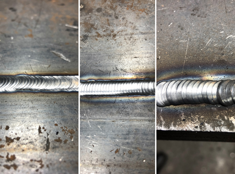
Why does my MIG weld look like spaghetti on top of the metal?
That is cold-lap or lack-of-fusion — voltage and wire speed are both too low for your metal thickness. The wire is depositing on top of the metal without melting into it. Increase voltage by 1-2 volts and wire speed by 25-50 IPM, then re-test on scrap.
Can I weld thicker metal by just turning up the voltage?
No. Thicker metal needs both higher voltage AND higher wire speed (more amperage), plus a larger wire diameter. Above 1/4-inch thick steel, single-pass welds become impractical and multi-pass technique is the standard approach.
How accurate are the settings charts inside MIG welder doors?
They are accurate for the conditions assumed (clean steel, 75/25 gas, ideal joint). Real-world conditions push the actual optimum 10-30 percent off chart values. Always treat door charts as starting points and fine-tune on a scrap piece before the project weld.
The Setting Most Welders Ignore
If your bead is wrong despite chart-perfect voltage and wire speed, check stick-out. Beginners drift to longer stick-out (3/4 inch or more) because it feels easier to see the puddle, but longer stick-out adds resistance and lowers effective amperage — real-world tests show a meaningful drop from just an extra 1/4-3/8 inch of extension. Pull the gun closer to the work — 1/2 to 5/8 inch from contact tip to workpiece — and most “wrong settings” beads suddenly look right. The hour I spent re-tuning my settings chart taught me less than the day I started measuring stick-out.
Related Articles
- MIG Welding Complete Guide
- MIG Weld Spatter: 10 Causes and Fixes
- MIG Welder Burning Through Wire
- Welding Porosity Causes and Fixes
- Welding Troubleshooting Guide
- Best Budget Welder Under $300
- Tungsten Electrode Color Chart
- Cost to Start Welding at Home
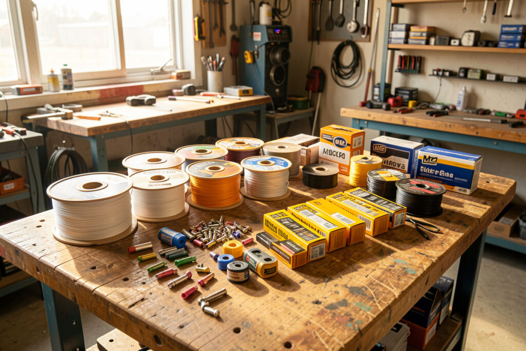
- Welding Consumables Guide
- Welding for Beginners
- Essential Welding Equipment Guide
Discussion (0)