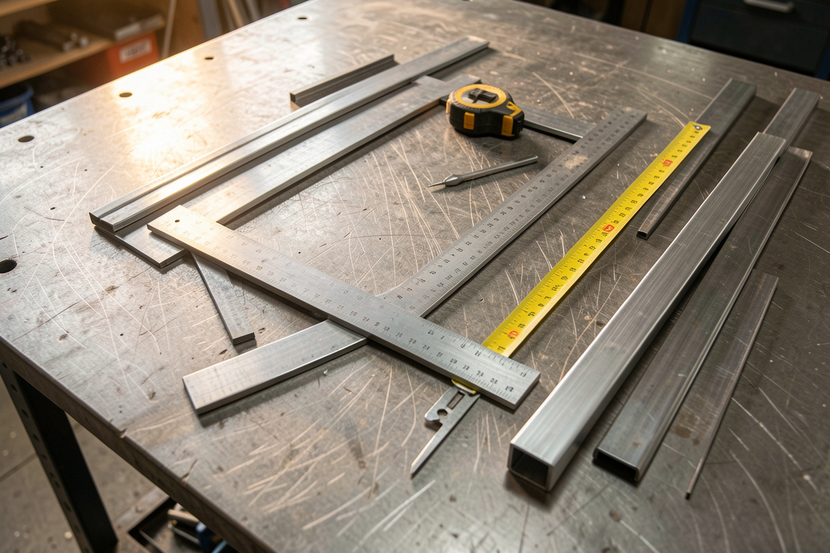

Metal fabrication is the skill of turning flat, raw stock into an accurate welded assembly — and 90% of that work happens before the arc ever strikes. On my bench a clean bracket starts with a layout line, a square cut, and a tight fit-up; the welding is the last 10%. Get the layout right and the weld almost falls into place. Get it wrong and no amount of arc time saves the part.
I run a YesWelder MIG-PRO205DS double-pulse MIG as my daily driver, but the machine is not where most of my fabrication time goes. It goes into measuring, marking, squaring, cutting, and clamping — the unglamorous half of the trade that decides whether the finished frame sits flat or rocks on the floor. This guide is the map for that half: how a piece of steel becomes a part, the order I do it in, and the six core skills that carry the whole process. Each one has its own deep-dive guide linked below.
What Fabrication Actually Means on a Home Bench
Fabrication is the process of cutting, shaping, and joining metal stock into a finished structure. For a home welder that means taking a length of angle iron, square tube, or flat bar and converting it — through layout, cutting, and fit-up — into a frame, bracket, cart, or jig that is square, the right size, and ready to weld. The welding joins it; fabrication makes it correct.
People come to welding thinking the puddle is the hard part. It is not. After a few hundred hours the arc becomes muscle memory. What separates a part that looks shop-built from one that looks like a first project is the geometry — whether the corners are 90 degrees, whether the legs are the same length, whether the joints close up with no daylight. That is all fabrication, and it is learnable in a weekend even if the welding takes a year. If you are still building those welding fundamentals, my complete MIG welding guide and the welding for beginners guide cover the arc side; this page covers everything that feeds it.
The Layout-First Mindset: Why Crooked Cuts Make Crooked Welds
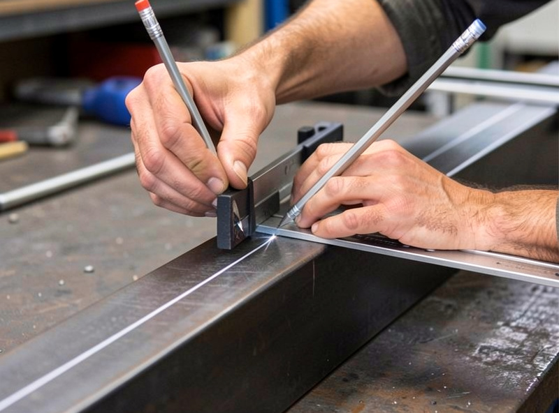
Every fabrication error compounds. A cut that is 2 degrees off square leaves a gap on one side of the joint. You can bridge that gap with weld, but the part is now pulling crooked, the heat input is uneven, and the whole assembly walks out of true as it cools. The fix was never at the welder — it was at the chop saw, three steps earlier.
This is the single idea that took me longest to internalize: the weld can only be as accurate as the fit-up, and the fit-up can only be as accurate as the cut and the layout. Mike, my welder friend with decades in the trade, says it the blunt way — “you can’t weld your way out of bad layout.” He is right. So I treat layout as the foundation and I do not rush it. Five minutes with a square and a scribe saves an hour of grinding, shimming, and cursing later. When you skip it, you end up chasing distortion and re-cutting parts, which is slower than doing it right the first time.
The home-bench reality is that you do not have a CNC bed or a fixture table from a fab shop. You have a flat-ish welding table, a square, a tape, a scribe, and clamps. The good news: that is genuinely enough to build accurate parts. The skill is in the habits, not the equipment budget.
The Fabrication Workflow, Start to Finish
Here is the order I work in for almost every part, from a simple bracket to the shop fixtures feeding toward the aluminum boat I am building skills for. Each stage feeds the next, and each has a dedicated guide.
- Layout and marking — transferring your dimensions onto the metal as clean, visible lines. See the metal layout and marking guide.
- Squaring and measuring — establishing a true reference edge and confirming every dimension before you cut. See squaring and measuring for fabrication.
- Scribing and punching — making marks that survive grinding and cutting, and dimpling hole centers so the drill bit does not wander. See the scribing and punching guide.
- Cutting to length — getting square, accurate ends so parts meet with no gap. See cutting metal to length.
- Fitting and tacking — holding the parts in position and locking the assembly with small welds before you commit. See fitting and tacking before welding.
- Fit-up tolerances — knowing how tight the joints actually need to be for the process and metal you are running. See fit-up tolerances for welding.
Read those six in order and you have the entire fabrication side of home welding. The rest of this hub walks each one at a working level so you understand how they connect before you go deep.
Layout and Marking: Getting Lines on Metal
Layout is transferring the dimensions from your plan onto the steel. It sounds trivial until you try to mark a clean, repeatable line on dark mill scale with a pencil that does not show. The trade uses soapstone, silver-streak pencils, and layout dye for exactly this reason — a line you cannot see is a line you cannot cut to.
On mild steel I keep a flat soapstone for rough lines and a silver-streak (a hard metal pencil) for fine, accurate ones. For precision work — hole centers, close-tolerance cuts — I brush on layout fluid (a blue dye) and scribe through it, so the bright scratch stands out against the blue. The marking tool changes with the accuracy you need. A framing layout tolerant to a millimeter gets soapstone; a bracket that has to bolt to an existing hole pattern gets dye and a scribe.
The key habit is marking from a single reference edge, never from a cut you just made. Every measurement on a part should originate from the same true edge, so errors do not stack. I cover the full toolkit, the marking media, and the reference-edge discipline in the layout and marking guide. It also explains why a center-finding square and a combination square earn their place over a cheap try square.
Squaring and Measuring: The Reference Everything Hangs Off
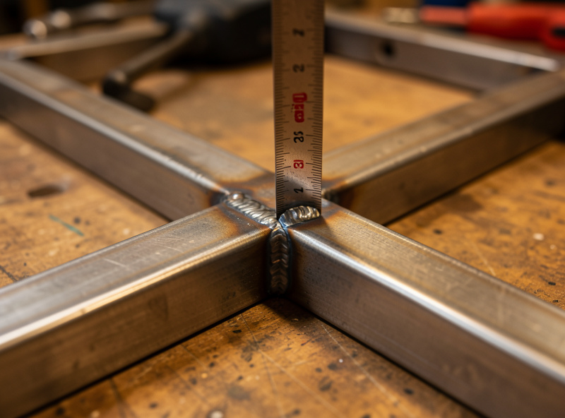
Square is the reference that the entire part is built against. If your reference edge is not straight and your corners are not 90 degrees, every other dimension is measured from a lie. I check square constantly — before cutting, after cutting, during fit-up, and again after tacking — because steel moves and a part can be perfect at fit-up and 2 degrees out after the first tack.
My measuring kit is deliberately simple: a good combination square, a 12-inch machinist square for checking 90s, a framing square for larger work, a quality tape, and a 24-inch level for long assemblies. The combination square is the one I reach for most — it sets depth, checks 45s and 90s, and marks parallel lines off the reference edge in one tool. For checking a finished frame I use the diagonal method: measure corner to corner both ways, and if the two diagonals match, the rectangle is square. That trick needs no special tool and it never lies. For anything that has to meet a spec, AWS D1.1 publishes allowable dimensional and straightness tolerances for finished weldments; for shop fixtures, matched diagonals are tolerance enough.
Accuracy in measuring is also about technique — reading the tape from the same reference, accounting for the “burn an inch” trick when the tape hook is unreliable, and never trusting a factory edge to be straight. The full method, including how I square up a four-sided frame and hold it there, is in squaring and measuring for fabrication. The squares, magnets, and clamps that make it possible are covered in my welding clamps, magnets, and squares guide.
Scribing and Punching: Marks That Survive
A pencil line burns off the instant a cutting disc touches it, and mill scale flakes away with the heat. For marks that survive cutting and grinding, you scribe — cutting a fine permanent line into the surface with a hardened steel or carbide tip. Scribed lines are the gold standard for accuracy because the tip rides tight against your square and leaves a line a few thousandths wide, far finer than any pencil.
Punching is the partner skill. A center punch dimples the exact spot where a drill bit should start, giving the bit a cone to seat in so it does not skate across the surface and wander off your mark. For a hole that has to land on a layout intersection, I punch the center first, then start with a small pilot bit. Skip the punch and the bit walks — I have ruined parts that way, drilling a hole 3 mm off where it needed to be on a mounting plate.
There is also a layout-punch technique for transferring hole patterns from an existing part: clamp the parts together, run a transfer punch through the existing holes, and the dimples land exactly where the new holes go. That single trick has saved me on every bracket that had to bolt to something already built. The full method for scribing accurate lines and using center, prick, and transfer punches is in the scribing and punching guide.
Cutting to Length: Square Ends or Nothing Fits
This is where layout becomes physical, and where most home fabrication goes wrong. A cut that is off-square leaves a joint that gaps on one side. A cut that is long throws every downstream dimension. The tool matters less than the technique — but the tool does matter, and for repeatable square ends on tube and bar I reach for a metal chop saw (abrasive or cold-cut) far more than the grinder.
For straight, accurate cuts I use one of three tools depending on the work: a metal-cutting chop saw for square ends on tube and angle, a portable band saw for thicker stock and cleaner kerfs, and my DeWalt DWE402 angle grinder with a thin cut-off wheel for freehand and on-the-frame trimming. Each has a place. The chop saw is fastest and squarest for repeated cuts to the same length using a stop block; the band saw wastes the least material and runs cool; the grinder is the most versatile but the least accurate, so I save it for cuts I will clean up afterward. I compare all three in chop saw vs band saw vs angle grinder, and the cut-off and flap discs that do the work are in my angle grinder guide for welders.
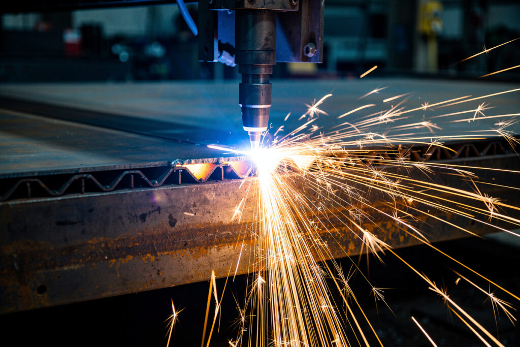
The single most useful cutting habit is the stop block: clamp a block to your saw fence at the target length and every piece comes off identical, no re-measuring. For square ends on round and square tube, a good chop saw with a sharp blade beats freehanding every time. The full cutting method, including accounting for kerf width and how I cut miters that actually close, is in the cutting metal to length guide. For plate and sheet, plasma and the straight-line plasma cutting method take over.
Fitting and Tacking: Holding It Before You Burn It In
Fit-up is assembling the cut parts into their final position and holding them there. Tacking is locking that position with small, strong welds before you lay the full beads. This is the stage where a careful fabricator pulls ahead, because a part that is clamped square and tacked square will weld out square — and a part that is rushed into final welds will pull every which way as it cools.
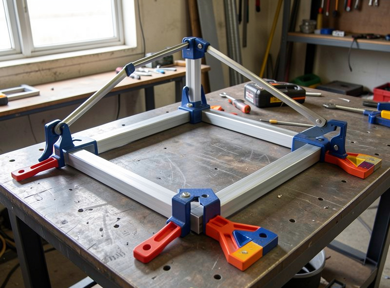
My fixturing kit does the holding: Bessey GSCC sliding-arm clamps on the table, a set of strong magnets to hold 90-degree corners, and the welding table itself as a flat reference. I clamp the part, check square with a machinist square, then put a tack at each joint. The order matters — I tack one corner, re-check the whole assembly, then tack the diagonal corner, re-check again, and only then fill in the rest. That sequence catches movement before it becomes permanent.
A good tack is small but fully fused — it has to hold against the shrinkage of the real welds. A cold tack that has not penetrated will crack and let the part move, which is worse than no tack at all. Once everything is tacked and confirmed square, I weld in a balanced sequence to control distortion, alternating sides so the heat does not pull the part one direction. The complete fit-up and tacking method, including tack size, spacing, and the check-tack-check rhythm, is in fitting and tacking before welding. Knowing which joint you are fitting helps too — see welding joint types.
Fit-Up Tolerances: How Tight Is Tight Enough
Not every joint needs to be machinist-tight, and chasing zero gap on a project that does not need it wastes hours. Fit-up tolerance is the gap you can accept and still get a sound weld — and it changes with the process, the metal, and the joint. A MIG butt joint on 3 mm steel tolerates a different gap than a TIG joint on stainless, and knowing the real numbers stops you from over-grinding or under-fitting.
As a working rule on my bench: for MIG on thin to medium steel I aim for a gap no wider than the wire diameter — a hair of light or less — because MIG does not bridge gaps well and a wide root just blows through or needs backing. For thicker plate I bevel the edges and intentionally leave a small root gap so the weld can reach the bottom. TIG wants the tightest fit of all, ideally metal-to-metal contact, because the filler is added by hand and there is no flux or extra wire to fill a void. Get the gap wrong and you invite lack of fusion or porosity. Code work spells these gaps out exactly — AWS D1.1, the structural welding code, tabulates prequalified root openings and bevel angles — but the home-bench rules above are what I actually fit to.
The point is that tolerance is a decision, not an accident. You decide how tight based on what you are welding, then you fit to that standard. The full breakdown — root gap by process and thickness, when to bevel, and how much misalignment a joint tolerates — is in the fit-up tolerances for welding guide.
The Home Fabrication Toolkit
You do not need a fab shop. You need a focused set of layout, cutting, and holding tools that earn their bench space. Here is what I actually reach for, what each does, and roughly what it costs to buy a version that will not frustrate you.
| Tool | Job in the workflow | Why it earns its place | Typical home cost |
|---|---|---|---|
| Combination square | Layout, squaring, depth, 45/90 checks | The single most-used measuring tool; do not buy the cheapest | $25–$60 |
| Machinist square (12 in) | Checking 90-degree corners at fit-up | True reference for tacking corners square | $20–$45 |
| Framing square | Large layout and frame squaring | Reaches across panels a small square cannot | $15–$30 |
| Quality tape measure | All length measurement | A reliable hook and clear marks prevent stacked errors | $15–$30 |
| Silver-streak / soapstone | Marking lines on steel | Visible on mill scale where pencil fails | $8–$15 |
| Scribe | Permanent precision lines | Survives cutting and grinding; finest line | $10–$20 |
| Center / transfer punch set | Hole starts, pattern transfer | Stops drill bits wandering off the mark | $12–$25 |
| Metal chop or band saw | Square cuts to length | Repeatable square ends with a stop block | $120–$400 |
| Angle grinder + discs | Cutting, bevel, cleanup | The versatile workhorse for prep and fit | $60–$150 |
| Sliding-arm clamps + magnets | Holding parts for fit-up | Free your hands to check square and tack | $40–$120 |
That whole list is a few hundred dollars and it covers every fabrication job a home shop will throw at you. Compared to the cost of the welder itself, it is the highest-leverage money you will spend — and it is what separates parts that look built from parts that look bodged. If you are still assembling the shop, my home welding workshop setup checklist and the first-year equipment checklist put it in context, and a flat welding table is the reference surface the whole toolkit relies on. A good combination square set is the one tool I would not cheap out on. As an Amazon Associate I earn from qualifying purchases.
Distortion: Fabrication’s Hidden Enemy
You can lay out, cut, fit, and tack a part dead-square and still pull it out of true the moment you weld it, because the weld shrinks as it cools and drags the metal toward it. This is why fabrication and welding are not separate jobs — the way you fit and tack directly controls how much the part moves under heat. A part that is tacked correctly and welded in a balanced sequence stays close to square; a part that is welded all down one side warps visibly.
My defenses are mechanical and procedural: clamp the part to the table or a heavy fixture so it physically cannot move, tack heavily on thin work, weld in short staggered segments rather than one long pass, and alternate sides to balance the heat. On a four-sided frame I never run all four welds the same direction. I treat distortion control as part of fit-up planning, not as a problem to fix afterward — because once a part has cooled crooked, straightening it is far harder than preventing it. The full set of techniques is in welding distortion control, and 3D-printed welding jigs and fixtures are a polymath-bench way to hold parts square while the heat goes in.
Common Fabrication Mistakes I See (and Made)
The errors that wreck home fabrication are predictable, and almost all of them trace back to skipping a layout or fit-up step to save a few minutes. Measuring from a cut edge instead of a reference edge so errors stack. Trusting a factory cut to be square when it never is. Marking with a pencil that burns off before you cut to it. Skipping the center punch and watching the drill bit skate. Tacking a part before checking it is square, then welding the error in permanently. Fitting a joint loose because grinding it tight felt like too much work, then fighting porosity and burn-through.
Every one of those is a five-minute discipline that prevents an hour of rework. The fabricators whose parts look professional are not faster welders — they are more patient at layout. I cover the broader set of new-welder errors in common beginner welding mistakes, and the metal-side knowledge — which steel type you are cutting and how much it weighs and costs — rounds out the planning side before any of it gets to the saw.
How It All Connects to the Welder
Fabrication is the work that makes the welder’s job easy. When the layout is accurate, the cuts are square, and the fit-up is tight, the weld is almost automatic — the puddle has somewhere to sit, the heat is even, and the part stays where you put it. When fabrication is sloppy, the welder spends the whole job compensating: bridging gaps, fighting distortion, grinding to fix what should have fit. That is why I tell anyone learning the trade to spend as much time with a square as with a torch. The same logic scales up: the shop fixtures and brackets I build now are practice for the aluminum boat — the hull will be won or lost at layout and fit-up long before the final welds go in. The CNC routes the templates, the printer makes the small parts, but the welder builds the structure, and fabrication is the language all three tools speak. Start with layout and marking and work down the list.
Frequently Asked Questions
What is metal fabrication in welding?
Metal fabrication is cutting, shaping, and joining metal stock into a finished structure. For a home welder it means turning angle, tube, or bar into a square, accurate part through layout, marking, cutting, and fit-up, then welding it together. The welding joins it; fabrication makes it correct and to size.
Do I need expensive tools to fabricate metal at home?
No. A combination square, a machinist square, a tape, a scribe, a punch set, a chop saw or band saw, an angle grinder, and a few clamps cover almost every home fabrication job for a few hundred dollars. The skill is in the layout and fit-up habits, not the equipment budget.
Why does my welded frame come out crooked even when I cut it carefully?
Usually it is distortion from welding, not cutting. The weld shrinks as it cools and pulls the part out of square. Fix it by clamping the part down, tacking it square first, then welding in short staggered segments and alternating sides to balance the heat instead of welding all down one direction.
How tight does a joint need to fit before welding?
It depends on the process. MIG on thin steel wants a gap no wider than the wire diameter. Thick plate gets a beveled edge and a small intentional root gap. TIG wants the tightest fit, ideally metal-to-metal contact, because the filler is added by hand with nothing to bridge a void.
What order should I do fabrication steps in?
Layout and marking first, then squaring and measuring to confirm, then scribing and punching for permanent marks and hole starts, then cutting to length, then fitting and tacking, and finally welding to the fit-up tolerance you set. Each stage feeds the next, so an error early compounds all the way down.
What is the most common fabrication mistake beginners make?
Measuring from a cut edge instead of a single true reference edge, which lets errors stack across the part. The second most common is tacking before checking square, which welds the error in permanently. Both are five-minute disciplines that prevent an hour of rework.
Related Guides in This Cluster
- Metal Layout and Marking Guide — getting accurate, visible lines onto steel
- Squaring and Measuring for Fabrication — the reference everything is built against
- Scribing and Punching Metal — marks that survive, holes that land
- Cutting Metal to Length — square ends so everything fits
- Fitting and Tacking Before Welding — holding it square before the arc
- Fit-Up Tolerances for Welding — how tight is tight enough

Discussion (0)